4
Effective November 2016
Installation Instructions for TMQV
Circuit Breakers and Molded Case Switches
3. Manual Operation
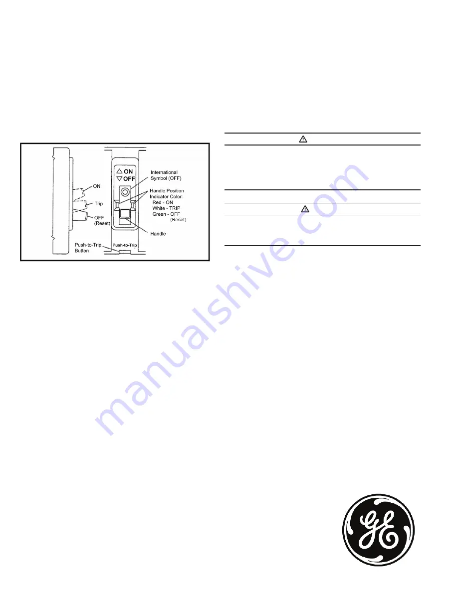
Manual operation of the circuit breaker is controlled by the circuit
breaker handle and the PUSH-TO-TRIP button. The circuit breaker
handle has three indicated positions, two of which are shown on
the cover with raised lettering to indicate ON and OFF. On the slid-
ing handle barrier, ON, OFF, and trip are also shown by a color-coded
strip for each circuit breaker handle position: red for ON, white for
tripped, and green for OFF. On the sliding handle barrier, ON/OFF is
also shown with the international symbols I/0 (See Fig. 4.)
Figure 4. Circuit Breaker Manual Controls.
Circuit Breaker Reset
After tripping, the circuit breaker is reset by moving the circuit break-
er handle to the extreme OFF position.
ote:
N
In the event of a thermal trip, the circuit breaker cannot be reset until
the thermal element cools.
PUSH-TO-TRIP Button
The PUSH-TO-TRIP button checks the tripping function and is used
to periodically exercise the operating mechanism.
4. Inspection and Field Testing
TMQV molded case circuit breakers are designed to provide years
of almost maintenance-free operation. The following procedure
describes how to inspect and test a circuit breaker in service.
Inspection
Circuit breakers in service should be inspected periodically. The
inspection should include the following checks 4-1 thru 4-7.
WARNING
BEFORE INSPECTING THE CIRCUIT BREAKER IN AN ELECTRICAL
SYSTEM, MAKE SURE THE CIRCUIT BREAKER IS SWITCHED TO THE OFF
POSITION AND THERE IS NO VOLTAGE PRESENT WHERE WORK IS TO BE
PERFORMED. SPECIAL ATTENTION SHOULD BE PAID TO REVERSE FEED
APPLICATIONS TO ENSURE NO VOLTAGE IS PRESENT. THE VOLTAGES IN
ENERGIZED EQUIPMENT CAN CAUSE INJURY OR DEATH.
CAUTION
MAKE SURE THAT CLEANING AGENTS OR SOLVENTS USED TO CLEAN
THE CIRCUIT BREAKER ARE SUITABLE FOR THE JOB. SOME COMMERCIAL
CLEANING AGENTS WILL DAMAGE THE NAME PLATES OR MOLDED
PARTS.
4-1. Remove dust, dirt, soot, grease, or moisture from the surface
of the circuit breaker using a lint-free dry cloth, brush, or vacuum
cleaner. Do not blow debris into circuit breaker. If contamination is
found, look for the source and eliminate the problem.
4-2. Switch circuit breaker to ON and OFF several times to be sure
that the mechanical linkages are free and do not bind. If mechanical
linkages are not free, replace circuit breaker.
4-3. Press the PUSH-TO-TRIP button to mechanically trip the circuit
breaker. Trip, reset, and switch circuit breaker ON several times. If
mechanism does not reset each time the circuit breaker is tripped,
replace the circuit
4-4. Check base, cover, and operating handle for cracks, chipping,
and discoloration. Circuit breakers should be replaced if cracks or
severe discoloration is found.
4-5. Check terminals and connectors for looseness or signs of over-
heating. Overheating will show as discoloration, melting, or blister-
ing of conductor insulation, or as pitting or melting of conductor sur-
faces due to arcing. If there is no evidence of overheating or loose-
ness, do not disturb or tighten the connections. If there is evidence
of overheating, terminations should be cleaned or replaced. Before
re-energizing the circuit breaker, all terminations and cable should be
refurbished to the condition when originally installed.
4-6. Check circuit breaker mounting hardware. Tighten if necessary.
4-7. Check area where circuit breaker is installed for any safety haz-
ards, including personal safety and fire hazards. Exposure to certain
types of chemicals can cause deterioration of electrical connections.
Field Testing
Any field testing should be done in accordance with applicable
NEMA Standards.
DEH41188 Installation Instructions
GE
41 Woodford Ave.
Plainville, CT 06062
© 2016 General Electric Company
Information provided is subject to change without notice. Please verify all details with GE.
All values are design or typical values when measured under laboratory conditions, and GE makes no warranty
or guarantee, express or implied, that such performance will be obtained under end-use conditions.


