5-62
745 Transformer Management Relay
GE Multilin
5.6 S4 ELEMENTS
5 SETPOINTS
5
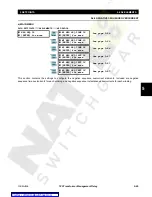
5.6.8 RESTRICTED GROUND (DIFFERENTIAL GROUND)
PATH: SETPOINTS
ÖØ
S4 ELEMENTS
ÖØ
RESTRICTED GROUND
Ö
W1(3) RESTD GND FAULT
Restricted Ground Fault protection is often applied to transformers having impedance grounded wye windings. It is
intended to provide sensitive ground fault detection for low magnitude fault currents which would not be detected by the
percent differential element.
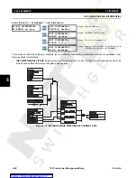
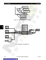
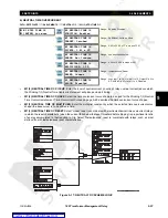
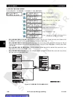
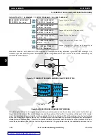
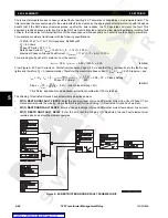
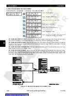
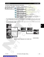
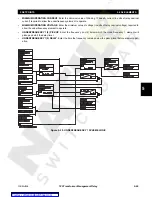
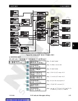
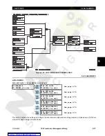
Figure 5–21: RESTRICTED EARTH GROUND FAULT PROTECTION
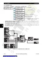
Figure 5–22: RESISTANCE GROUNDED WYE WIRING
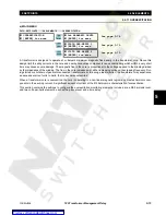
An internal ground fault on an impedance grounded wye winding (see second figure above) produces a fault current (I
F
)
dependent on the value of the ground impedance and the position of the fault on the winding with respect to the neutral
point. The resultant primary current (I
P
) will be negligible for faults on the lower 30% of the winding since the fault voltage
will not be the system voltage but the result of the transformation ratio between the primary windings and the percentage of
shorted turns on the secondary. Therefore, the resultant differential currents could be below the slope threshold of the per-
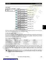
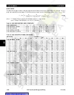
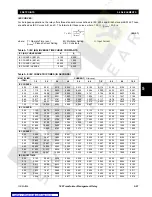
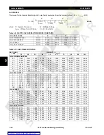
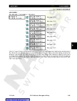
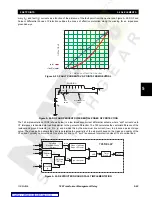
cent differential element and thus the fault could go undetected. The graph below shows the relationship between the pri-
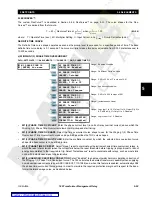
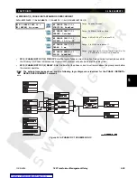
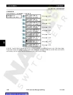
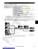
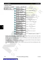
W1 RESTD GND FAULT
[ENTER] for more
W1 RESTD GND FAULT
FUNCTION: Disabled
Range: Enabled, Disabled
W1 RESTD GND FAULT
TARGET: Latched
Range: Self-Reset, Latched, None
W1 RESTD GND FAULT
PICKUP: 0.08 x CT
Range: 0.02 to 20.00 x CT in steps of 0.01
W1 RESTD GND FAULT
SLOPE: 10%
Range: 0 to 100% in steps of 1
W1 RESTD GND FAULT
DELAY: 0.10 s
Range: 0.00 to 600.00 s in steps of 0.01
W1 NEUTRAL TIME OC
BLOCK: Disabled
Range: Logc Inpt 1 to 16, Virt Inpt 1 to 16, Output Rly 2 to
8, SelfTest Rly, Vir Outpt 1 to 5, Disabled
ENTER
ESCAPE
ð
ð
MESSAGE
ESCAPE
MESSAGE
ESCAPE
MESSAGE
ESCAPE
MESSAGE
ESCAPE
MESSAGE
ESCAPE
87T
Rg
87TG
Wye Winding
FAULT
I
F
Delta Winding
I
P
Impedance grounded
wye winding

