GE Multilin
745 Transformer Management Relay
5-83
5 SETPOINTS
5.6 S4 ELEMENTS
5
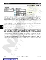
d) LOSS OF LIFE LIMIT
PATH: SETPOINTS
ÖØ
S4 ELEMENTS
ÖØ
INSULATION AGING
ÖØ
LOSS OF LIFE LIMIT
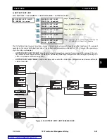
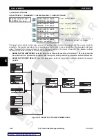
The Loss of Life Limit element computes the total expended life of the transformer, based on the aging factor and the actual
in-service time of the transformer. For example, if the aging factor is a steady 1.5 over a time period of 10 hours, the trans-
former will have aged for an equivalent 1.5
×
10 = 15 hours. The cumulative total number of hours expended is retained in
the relay even when control power is lost. The initial Loss of Life value, when a relay is first placed in service, can be pro-
grammed under the transformer settings. The element operates on the cumulative total value, with no time delay. The out-
put of this element should be used as an alarm only, as users may wish to leave the transformer in service beyond the
theoretical expended life.
Enter the expended life, in hours, required for operation of the element in the
LOSS OF LIFE PICKUP
setpoint. This setting
should be above the total life of the transformer, in hours. As an example, for a 15-year transformer, the total number of
hours would be 13140
×
10 = 131400.
The actual values are only displayed if the Loss of Life option is installed and the ambient temperature is
enabled.
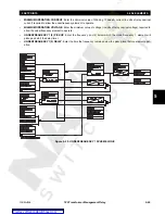
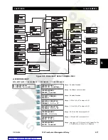
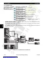
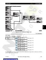
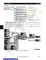
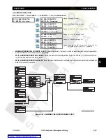
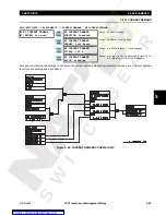
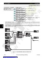
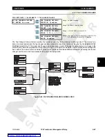
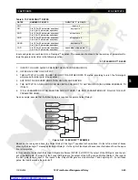
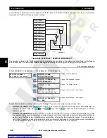
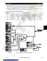
Figure 5–38: LOSS-OF-LIFE SCHEME LOGIC
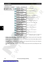
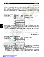
LOSS OF LIFE LIMIT
[ENTER] for more
LOSS OF LIFE LIMIT
FUNCTION: Disabled
Range: Enabled, Disabled
LOSS OF LIFE LIMIT
TARGET: Self-Reset
Range: Self-Reset, Latched, None
LOSS OF LIFE LIMIT
PICKUP: 16000 x 10h
Range: 0 to 20000 x 10h (providing for a maximum of
20000 hours) in steps of 1
LOSS OF LIFE LIMIT
BLOCK: Disabled
Range: Logc Inpt 1 to 16, Virt Inpt 1 to 16, Output Rly 2 to
8, SelfTest Rly, Vir Outpt 1 to 5, Disabled
ENTER
ESCAPE
ð
ð
MESSAGE
ESCAPE
MESSAGE
ESCAPE
MESSAGE
ESCAPE
NOTE

