6-18
745 Transformer Management Relay
GE Multilin
6.6 TARGET AND FLASH MESSAGES
6 ACTUAL VALUES
6
6.6TARGET AND FLASH MESSAGES
6.6.1 TARGET MESSAGES
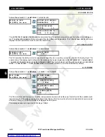
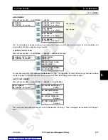
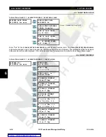
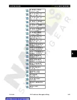
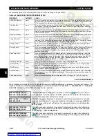
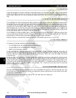
Target messages are displayed when any protection, monitoring or self-test target is activated. The messages contain
information about the type of the active target(s), and are displayed in a queue that is independent of both the setpoint and
actual value message structures.
When any target is active, the Message LED will turn on, and the first message in the queue is displayed automatically. The
target message queue may be scrolled through by pressing
. If no key is pressed, the next target message in the
queue will be displayed after a delay of four seconds. This process repeats, continuously cycling through the queue of tar-
get messages.
As long as there is at least one message in the queue, the Message LED will remain lit. Pressing any key other than
will return the display to the setpoint or actual value message that was previously displayed. The
key may be
pressed any time the Message LED is lit, to re-display the target message queue.
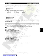
If
is pressed when no target messages are in the queue, all front-panel LEDs will light and the flash message
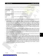
will appear. A typical active target message looks like this,
and consists of three components which are arranged as follows:
The
<STATUS>
part of the above message will be one of
PICKUP
,
OPERATE
or
LATCHED
:
•
PICKUP:
Indicates that the fault condition that is required to activate the protection element has been detected by the
745 but has not persisted for a sufficiently long time to cause the relay to activate its protection function.
•
OPERATE
: Indicates that the protection element has been activated.
•
LATCHED
: Indicates that the protection element is (or was) activated. This display will remain even if the conditions
that caused the element to activate are removed.
The
<PHASE>
part of the message represents the phase(s) that are associated with the element (where applicable).
Messages for
LATCHED
targets remain in the queue until the relay is reset. Messages for
PICKUP
and
OPERATE
targets
remain in the queue as long as the condition causing the target to be active is present. In addition, messages for
LATCHED
targets will automatically be deleted if an entire week passes without any changes to the state of the target messages but
the conditions that caused the
LATCHED
messages to be displayed originally are no longer present.
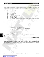
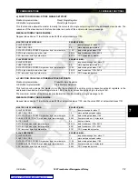
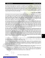
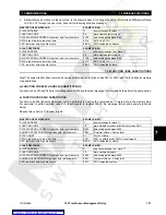
The bottom line of the display (i.e.,
<CAUSE>
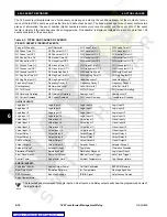
) will be the name of the element that has been activated. These are as fol-
lows:
NO ACTIVE TARGETS
(TESTING LEDS)
LATCHED: a
Percent Differentl
<STATUS>: <PHASE>
<CAUSE>
Percent Differentl
Inst Differential
W1 Phase Time OC
W2 Phase Time OC
W3 Phase Time OC
W1 Phase Inst OC 1
W2 Phase Inst OC 1
W3 Phase Inst OC 1
W1 Phase Inst OC 2
W2 Phase Inst OC 2
W3 Phase Inst OC 2
W1 Ntrl Time OC
W2 Ntrl Time OC
W3 Ntrl Time OC
W1 Ntrl Inst OC 1
W2 Ntrl Inst OC 1
W3 Ntrl Inst OC 1
W1 Ntrl Inst OC 2
W2 Ntrl Inst OC 2
W3 Ntrl Inst OC 2
W1 Gnd Time OC
W2 Gnd Time OC
W3 Gnd Time OC
W1 Gnd Inst OC 1
W2 Gnd Inst OC 1
W3 Gnd Inst OC 1
W1 Gnd Inst OC 2
W2 Gnd Inst OC 2
W3 Gnd Inst OC 2
W1 Rest Gnd Fault
W2 Rest Gnd Fault
W3 Rest Gnd Fault
W1 Neg Seq Time OC
W2 Neg Seq Time OC
W3 Neg Seq Time OC
W1 Neg Seq Inst OC
W2 Neg Seq Inst OC
W3 Neg Seq Inst OC
Underfrequency 1
Underfrequency 2
Freq Decay Rate 1
Freq Decay Rate 2
Freq Decay Rate 3
Freq Decay Rate 4
Overfrequency
5th Harmonic Level
Volts-per-hertz 1
Volts-per-hertz 2
W1 THD Level
W2 THD Level
W3 THD Level
W1 Harmonic Derating
W2 Harmonic Derating
W3 Harmonic Derating
Analog Level 1
Analog Level 2
W1 Current Demand
W2 Current Demand
W3 Current Demand
Xformer Overload
Logic Input 1 (to 16)
Virtual Input 1 (to 16)
NEXT
NEXT
NEXT
NEXT

