2-2
745 Transformer Management Relay
GE Multilin
2.1 USING THE FRONT PANEL DISPLAY
2 GETTING STARTED
2
9.
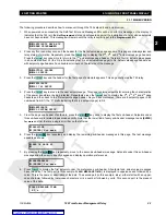
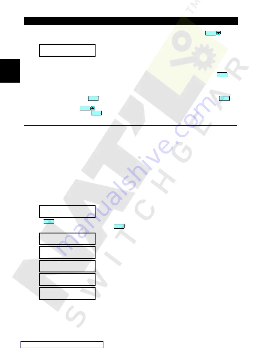
To view the remaining setpoints associated with the preferences sub-header, repeatedly press the
key. The
last message appears as shown.
Let us review how we got to this last message.
1.
First, we started at the setpoints page header
S1 745 SETUP
.
2.
We then moved to the second sub-header message in Page S1, which is
PREFERENCES
, and pressed the
key.
3.
We then moved to the last message in this group.
A path can be used as a means of specifying where a message is located in the 745 relay. For this last message, the path
would be
S1 745 SETUP
Ö
PREFERENCES
ÖØ
DEFAULT MESSAGE TIMEOUT
. For the purposes of this manual, we will refer to
messages in this manner. Press the
key to return to the preferences sub-header message. Pressing the
key
from any of the messages under a sub-header will return the display to that sub-header message. From a sub-header mes-
sage, the repeated pressing of
moves the display through the list of sub-header messages to the page header.
As an alternative, you could press the
key and move directly to the next page.
2.1.2 CHANGING SETPOINTS
a) DESCRIPTION
There are several different classes of setpoints, distinguished by the way their values are displayed and edited. This sec-
tion describes how to edit the values used by all setpoint classes.
Hardware and passcode security features are designed to provide protection against unauthorized setpoint changes. Since
we will be programming new setpoints using the front panel keys, a hardware jumper must be installed across the setpoint
access terminals (D9 and D10) on the back of the relay case. A keyswitch may also be used across these terminals to
enable setpoint access. Attempts to enter a new setpoint via the front panel without this connection will be unsuccessful.
b) NUMERICAL SETPOINTS
Each numerical setpoint has its own minimum, maximum, and increment value associated with it. These parameters define
what values are acceptable for a setpoint.
1.
Select the
S2 SYSTEM SETUP
ÖØ
VOLTAGE INPUT
ÖØ
NOMINAL VT SECONDARY VOLTAGE
setpoint.
2.
Press
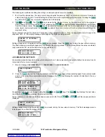
. The following context sensitive flash messages will sequentially appear for several seconds each. For
the case of a numerical setpoint message, the
key displays the minimum, maximum, and step value.
DEFAULT MESSAGE
TIMEOUT: 300 s
NOMINAL VT SECONDARY
VOLTAGE: 120.0 V
MINIMUM: 60.0
MAXIMUM: 120.0
IN STEPS OF:
0.1
PRESS (0)-(9) OR
VALUE
PRESS [ENTER] TO
STORE NEW VALUE
END OF PAGE S1
MESSAGE
ENTER
ESCAPE
ESCAPE
MESSAGE
SETPOINT
HELP
HELP

