7-30
745 Transformer Management Relay
GE Multilin
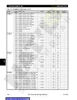
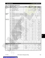
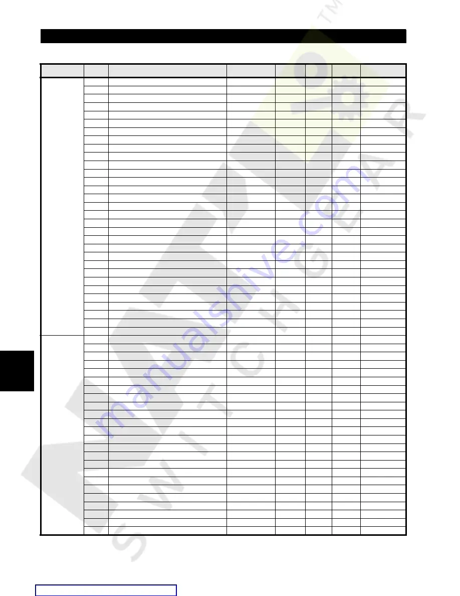
7.4 MODBUS MEMORY MAP
7 COMMUNICATIONS
7
ANALOG
OUTPUTS
continued
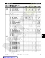
12D7
Analog Output 2 Range
---
---
---
F26
2 = 4-20 mA
12D8
Analog Output 2 Minimum
---
---
---
---
0 A
12D9
Analog Output 2 Maximum
---
---
---
---
1000 A
12DA
Analog Output 3 Function
---
---
---
F30
0 = Disabled
12DB
Analog Output 3 Value
---
---
---
F45
2 = W1 øC curr
12DC
Analog Output 3 Range
---
---
---
F26
2 = 4-20 mA
12DD
Analog Output 3 Minimum
---
---
---
---
0 A
12DE
Analog Output 3 Maximum
---
---
---
---
1000 A
12DF
Analog Output 4 Function
---
---
---
F30
0 = Disabled
12E0
Analog Output 4 Value
---
---
---
F45
9 = W1 loading
12E1
Analog Output 4 Range
---
---
---
F26
2 = 4-20 mA
12E2
Analog Output 4 Minimum
---
---
---
---
0%
12E3
Analog Output 4 Maximum
---
---
---
---
100%
12E4
Analog Output 5 Function
---
---
---
F30
0 = Disabled
12E5
Analog Output 5 Value
---
---
---
F45
26 = Voltage
12E6
Analog Output 5 Range
---
---
---
F26
2 = 4-20 mA
12E7
Analog Output 5 Minimum
---
---
---
---
0 = 0.00 kV
12E8
Analog Output 5 Maximum
---
---
---
---
14.40 kV
12E9
Analog Output 6 Function
---
---
---
F30
0 = Disabled
12EA
Analog Output 6 Value
---
---
---
F45
24 = frequency
12EB
Analog Output 6 Range
---
---
---
F26
2 = 4-20 mA
12EC
Analog Output 6 Minimum
---
---
---
---
5700 = 57.0 Hz
12ED
Analog Output 6 Maximum
---
---
---
---
6300 = 63.0 Hz
12EE
Analog Output 7 Function
---
---
---
F30
0 = Disabled
12EF
Analog Output 7 Value
---
---
---
F45
25 = Tap Pos.
12F0
Analog Output 7 Range
---
---
---
F26
2 = 4-20 mA
12F1
Analog Output 7 Minimum
---
---
---
---
1
12F2
Analog Output 7 Maximum
---
---
---
---
33
12F3
Reserved
↓
↓
↓
↓
↓
↓
↓
12FF
Reserved
LOGIC INPUTS
1300
Logic Input 1 Function
---
---
---
F30
0 = Disabled
1301
Logic Input 1 Name (9 registers)
---
---
---
F33
"Logic Input 1"
130A
Logic Input 1 Asserted State
---
---
---
F75
1 = Closed
130B
Logic Input 2 Function
---
---
---
F30
0 = Disabled
130C
Logic Input 2 Name (9 registers)
---
---
---
F33
"Logic Input 2"
1315
Logic Input 2 Asserted State
---
---
---
F75
1 = Closed
1316
Logic Input 3 Function
---
---
---
F30
0 = Disabled
1317
Logic Input 3 Name (9 registers)
---
---
---
F33
"Logic Input 3"
1320
Logic Input 3 Asserted State
---
---
---
F75
1 = Closed
1321
Logic Input 4 Function
---
---
---
F30
0 = Disabled
1322
Logic Input 4 Name (9 registers)
---
---
---
F33
"Logic Input 4"
132B
Logic Input 4 Asserted State
---
---
---
F75
1 = Closed
132C
Logic Input 5 Function
---
---
---
F30
0 = Disabled
132D
Logic Input 5 Name (9 registers)
---
---
---
F33
"Logic Input 5"
1336
Logic Input 5 Asserted State
---
---
---
F75
1 = Closed
1337
Logic Input 6 Function
---
---
---
F30
0 = Disabled
1338
Logic Input 6 Name (9 registers)
---
---
---
F33
"Logic Input 6"
1341
Logic Input 6 Asserted State
---
---
---
F75
1 = Closed
1342
Logic Input 7 Function
---
---
---
F30
0 = Disabled
1343
Logic Input 7 Name (9 registers)
---
---
---
F33
"Logic Input 7"
134C
Logic Input 7 Asserted State
---
---
---
F75
1 = Closed
134D
Logic Input 8 Function
---
---
---
F30
0 = Disabled
134E
Logic Input 8 Name (9 registers)
---
---
---
F33
"Logic Input 8"
1357
Logic Input 8 Asserted State
---
---
---
F75
1 = Closed
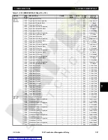
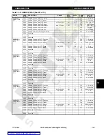
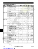
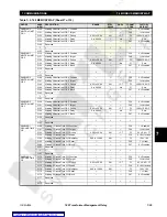
Table 7–5: 745 MEMORY MAP (Sheet 18 of 35)
GROUP
ADDR
(HEX)
DESCRIPTION
RANGE
STEP
VALUE
UNITS
FORMAT
CODE
FACTORY
DEFAULT

