GE Multilin
745 Transformer Management Relay
4-1
4 HUMAN INTERFACES
4.1 HARDWARE INTERFACE
4
4 HUMAN INTERFACES 4.1HARDWARE INTERFACE
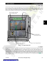
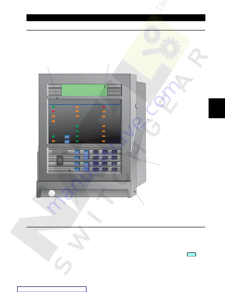
4.1.1 FRONT PANEL
The front panel provides a local operator interface with a 40-character liquid crystal display, LED status indicators, control
keys, and program port. The display and status indicators update alarm and status information automatically. The control
keys are used to select the appropriate message for entering setpoints or displaying measured values. The RS232 pro-
gram port is also provided for connection with a computer running the 745PC software.
Figure 4–1: 745 FRONT PANEL VIEW
4.1.2 DISPLAY
All messages are displayed in English on the 40-character liquid crystal display, which is backlit for visibility under varied
lighting conditions. When the keypad and display are not actively being used, the screen sequentially displays up to 30
user-selected default messages providing system information. These messages appear after a time of inactivity that is pro-
grammable by the user. Pressing any key after default messages have appeared will return the display to the last message
displayed before the default messages appeared. Trip and alarm condition messages automatically override default mes-
sages. All display pixels are illuminated briefly during power up self-testing, and can be energized by pressing
when
no trips or alarms are active.
745
Transformer Management Relay
™
FrontPanel.CDR
IN SERVICE
LOCAL
SETPOINT GROUP 2
LOAD-LIMIT
REDUCED
TRIP
SELF-TEST
ERROR
SETPOINT GROUP 3
TRANSFORMER
DE-ENERGIZED
ALARM
PICKUP
TEST MODE
TRANSFORMER
OVERLOAD
SETPOINT GROUP 1
PHASE A
PHASE B
PHASE C
GROUND
MESSAGE
PROGRAM PORT
SETPOINT
7
8
9
4
5
6
1
2
3
.
0
HELP
MESSAGE
VALUE
ACTUAL
ESCAPE
ENTER
RESET
NEXT
DIFFERENTIAL
BLOCKED
745 STATUS
SYSTEM STATUS
CONDITIONS
SETPOINT GROUP 4
g
745 TRANSFORMER
MANAGEMENT RELAY
DISPLAY
STATUS INDICATORS AND
LOCAL CONTROL KEYS
SETPOINT ENTRY
AND MONITOR KEYS
HANDLE TO WITHDRAW RELAY
PROGRAM PORT INTERFACE
TO LOCAL COMPUTER
NEXT

