GE Multilin
745 Transformer Management Relay
1-1
1 PRODUCT OVERVIEW
1.1 INTRODUCTION
1
1 PRODUCT OVERVIEW 1.1INTRODUCTION
1.1.1 DESCRIPTION
These instructions do not purport to cover all details or variations in equipment nor provide for every possible con-
tingency to be met in connection with installation, operation, or maintenance. Should further information be desired
or should particular problems arise which are not covered sufficiently for the purchaser’s purpose, the matter
should be referred to the General Electric Company.
To the extent required the products described herein meet applicable ANSI, IEEE, and NEMA standards; but no
such assurance is given with respect to local codes and ordinances because they vary greatly.
The 745 Transformer Management Relay™ is a high speed, multi-processor based, three-phase, two or three winding,
transformer management relay intended for the primary protection and management of small, medium and large power
transformers. The 745 combines Percent Differential, Overcurrent, Frequency, and Overexcitation protection elements
along with monitoring of individual harmonics, and THD in one economical package.
The relay provides a variety of adaptive relaying features:
•
Adaptive Harmonic Restraint which addresses the problem of false tripping during inrush
•
Adaptive Time Overcurrent Elements which will adjust their pickup settings based on the calculated transformer capa-
bility when supplying load currents with high harmonic content
•
Multiple Setpoint Groups which allow the user to enter and dynamically select from up to four groups of relay settings
to address the protection requirements of different power system configurations
•
Dynamic CT Ratio Mismatch Correction which monitors the on-load tap position and automatically corrects for CT ratio
mismatch
•
FlexLogic™ which allows PLC style equations based on logic inputs and protection elements to be assigned to any of
the 745 outputs.
The 745 also includes a powerful testing and simulation feature. This allows the protection engineer the ability to test the
relay operation based on captured or computer generated waveform data which can be converted to a digitized format and
downloaded into the 745’s simulation buffer for “playback”. A Waveform Capture function that records waveform data for
fault, inrush, or alarm conditions is also provided.
The Auto-Configuration function eliminates the need for any special CT connections by having all CTs connected in wye.
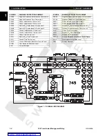
1.1.2 PROTECTION FEATURES SUMMARY
SYMBOL
COMMON PROTECTION ELEMENT
SYMBOL
WINDING 1 PROTECTION ELEMENT
59/81-1
Volts-Per-Hertz 1
150/46
Negative Sequence Instantaneous Overcurrent
59/81-2
Volts-Per-Hertz 2
151/46
Negative Sequence Time Overcurrent
81U-1
Underfrequency 1
150P1
Phase Instantaneous Overcurrent 1
81U-2
Underfrequency 2
150P2
Phase Instantaneous Overcurrent 2
81U-R1
Frequency Decay Rate 1
150N1
Neutral (3I
0
) Instantaneous Overcurrent 1
81U-R2
Frequency Decay Rate 2
150N2
Neutral (3I
0
) Instantaneous Overcurrent 2
81U-R3
Frequency Decay Rate 3
150G1
Ground Instantaneous Overcurrent 1
81U-R4
Frequency Decay Rate 4
150G2
Ground Instantaneous Overcurrent 2
81-H5
5th Harmonic Level
151P
Phase Time Overcurrent
81O
Overfrequency
151N
Neutral (3I
0
) Time Overcurrent
87
Differential (Percent)
151G
Ground Time Overcurrent
50/87
Instantaneous Differential
187TG
Ground Differential (Restricted Ground Fault)
AN-1
Analog Input Level 1
1THD
Total Harmonic Distortion Level
AN-2
Analog Input Level 2
1AD
Current Demand
Insulation Aging:
•
Aging Factor
•
Hottest Spot Limit
•
Total Accumulated Life
Tap Changer Monitor
NOTE

