background image

9-12

Transport Pro

Revision A

2012659-042

Checkout: Recommended Tests and Checkout Procedures

green. The batteries may require up to four hours to charge.

‹

If the battery “fuel gauge” displays the word “ERROR,” the 
battery may be asleep. 

6. Verify an audio “Beep” tone sounds at the end of Boot up.

7. Verify the operation of the 

TRIM KNOB

 control.

a. Rotate the 

TRIM KNOB

 control to scroll through several menus.

b. Press the 

TRIM KNOB

 control on a menu option to verify the 

menu is selectable.

8. Verify the operation of the control keys. 

‹

Verify that an audio “Beep” tone sounds after each control panel 
key is pressed.

9. Check battery power for both batteries.

a. Unplug the monitor from the AC power source. Verify the 

monitor stays on.

b. Remove a battery and verify that the monitor stays on. 

c. Reinsert the battery and remove the other battery. Verify that 

the monitor stays on.

d. Reinstall battery and plug the monitor into an AC power source.

Battery Function Test

The battery application software will behave differently depending on 
whether a acquisition device is connected. This fact also applies to which 
device was the “last” device that was connected. Throughout this 
document, when reference is made to a device being “connected”, this 
also applies to the device being connected and then disconnected, without 
a different device being connected.

1. With the monitor on, disconnect the power supply from the monitor.

2. Verify the 

battery 

Power

 indicator illuminates. This indicates 

operation from the monitor’s battery power.

3. Insert a TRAM module into the TRAM chute.

4. Connect the TRAM communication cable to the monitor and verify 

an ECG parameter box is displayed. This indicates the TRAM 
module can be run from battery power.

5. Connect the power supply to the monitor.

6. Verify the DC power indicator illuminates. This indicates the 

monitor is operating from the AC power source.

7. Verify the 

CHARGING STATUS

 indicator illuminates for a few 

minutes. 

‹

An amber glow indicates the monitor’s battery is charging.

‹

A green glow indicates the monitor’s batteries are fully charged.

Summary of Contents for Transport Pro

Page 1: ...Transport Pro Patient Monitor Service Manual Software Version 2 2024579 018 Revision A ...

Page 2: ...r software versions Listed below are GE Medical Systems Information Technologies trademarks used in this document All other trademarks contained herein are the property of their respective owners TRAM TRAM RAC TRIM KNOB and UNITY NETWORK are trademarks of GE Medical Systems Information Technologies registered in the United States Patent and Trademark Office TRANSPORT PRO and UNITY are trademarks o...

Page 3: ...ral 2 2 Safety Information 2 2 Manufacturer s Responsibility 2 2 Classification Information 2 2 EN 2 2 Underwriter s Laboratories Inc 2 3 Equipment Symbols 2 3 Equipment Identification 2 4 Views 2 5 Front 2 5 Rear 2 6 Side 2 7 Controls 2 8 TRIM KNOB Control 2 8 Power Key 2 8 Function Keys 2 8 Indicators 2 8 DC Power 2 9 Battery Power 2 9 Battery Charge Status 2 9 Battery In Use 2 9 Alarm Light 2 1...

Page 4: ... Supply 2 12 TRAM Chute 2 12 TRAM Module 2 13 TRAM Communication Cable 2 13 Optional Component 2 13 Cadex SMart Two External Battery Charger 2 13 Theory of Operation 2 14 Processor Power Management 2 14 LCD Backlight Inverter 2 15 Alarm Light 2 15 Battery Interface 2 15 Speaker 2 15 3 Installation 3 1 Location Requirements 3 2 Battery 3 3 Software 3 4 Mounting Options 3 4 ...

Page 5: ...t Name 4 4 Bed Number 4 4 Country Selection 4 4 Language 4 5 5 Maintenance 5 1 Maintenance Schedule 5 2 Manufacturer Recommendations 5 2 Manufacturer Responsibility 5 2 Maintenance Checklist 5 3 Inspection and Cleaning 5 4 Visual Inspection 5 4 Cleaning Cautions 5 4 Cleaning Recommendations 5 5 Battery 5 5 General 5 5 Use Recommendations 5 6 Storage Recommendations 5 6 Waking Up 5 6 External 5 6 I...

Page 6: ...m 6 4 Display Flickering 6 4 Display Bad Quality 6 4 Missing Inaccurate Patient Data Waveforms 6 5 Speaker Buzz 6 5 During Alarms 6 5 Always 6 5 Unresponsive Buttons 6 5 Error Messages 6 6 Power Sources 6 7 Service Menu 6 7 Boot Loader Service Menu 6 8 Service Mode Menu 6 8 Review Errors 6 8 Battery Service 6 10 7 Ordering Parts 7 1 Overview 7 2 Exploded View 7 3 Field Replaceable Units 7 4 Access...

Page 7: ...7 Display Subassembly 8 7 Main Processor PCB Subassembly 8 9 Front Plastic Subassembly 8 11 Speaker 8 12 Inverter PCB 8 13 Alarm Light 8 14 ePort Flex Circuit 8 15 Foot 8 16 Battery Doors 8 17 Handle 8 18 TRAM 8 19 9 Checkout 9 1 Electrical Safety Tests 9 2 General 9 2 Conditions 9 2 Required Equipment 9 2 Recommended Tests 9 2 Power Outlet 9 3 Ground Earth Integrity 9 4 Ground Earth Wire Leakage ...

Page 8: ...st 9 13 Completion 9 14 PM Form 9 14 Appendices Technical Specifications Physical A 2 Environmental A 2 Certification A 2 Display A 3 Battery A 3 External Power Supply A 3 Electromagnetic Compatibility Electromagnetic Compatibility EMC B 2 Guidance and Manufacturer s Declaration Electromagnetic Emissions B 2 Guidance and Manufacturer s Declaration Electromagnetic Immunity B 3 Recommended Separatio...

Page 9: ...Revision A Transport Pro 1 1 2012659 042 1 Introduction ...

Page 10: ...nded use Intended Audience This manual is intended for service representatives and technical personnel who maintain troubleshoot or repair this monitor Manual Conventions Revision History Each page of this manual has a revision letter located at the bottom of the page It identifies the revision level of the entire manual Ordering Manuals To order additional copies of this manual call Accessories a...

Page 11: ...s defined as a source of potential injury to a person DANGER Indicates an imminent hazard which if not avoided will result in death or serious injury WARNING Indicates a potential hazard or unsafe practice which if not avoided could result in death or serious injury CAUTION Indicates a potential hazard or unsafe practice which if not avoided could result in minor personal injury or product propert...

Page 12: ...1 4 Transport Pro Revision A 2012659 042 Introduction Safety Message Definitions ...

Page 13: ...Revision A Transport Pro 2 1 2012659 042 2 Equipment Overview ...

Page 14: ...ion before connecting any devices to the equipment that are not recommended in this manual Parts and accessories used must meet the requirements of the applicable EN 60601 series safety standards and or the system configuration must meet the requirements of the EN 60601 1 1 medical electrical systems standard Periodically and whenever the integrity of the device is in doubt test all functions The ...

Page 15: ...l Equipment With respect to electric shock fire and mechanical hazards only in accordance with UL 60601 1 and CAN CSA C22 2 NO 601 and EN 60601 1 Equipment Symbols ATTENTION Consult accompanying documents before using the equipment Power NBP Go Stop Zero All Silence Alarm Battery DC power Ethernet Video In ...

Page 16: ...GE device has a unique serial number for identification A sample of the information found on a serial number label is shown below Description A Product code AAD B Year manufactured C Fiscal week manufactured D Production sequence number E Manufacturing site F Miscellaneous characteristic A B C D E F ...

Page 17: ...Revision A Transport Pro 2 5 2012659 042 Equipment Overview Views Views Front Description 1 Alarm light 2 Controls and indicators 2 602A 1 ...

Page 18: ...ar Description 1 Serial number label 2 Video In TRAM connector 3 Ethernet Service connector 4 Main processor diagnostic LEDs Light Emitting Diodes 5 Mounting points 6 ePort connector 7 TRAM chute mounting slots 8 TRAM chute monitor mounting slot 1 2 3 4 5 6 7 603A 7 5 8 ...

Page 19: ... Pro 2 7 2012659 042 Equipment Overview Views Side Description 1 DC power connector 2 Video In connector 3 TRAM module 4 TRAM communication cable 5 TRAM chute 6 Cable management tray 7 Battery doors 7 3 4 5 604A 606A 6 1 2 ...

Page 20: ... using the optional power supply this key turns the monitoring standby mode on and off When the standby mode is turned on patient monitoring is discontinued However patient data already accumulated is retained and the battery charging function continues Function Keys Three fixed function keys are provided for NBP Go Stop Zero All and Silence Alarm See the operator s manual for more information Ind...

Page 21: ...s powered by the external power supply Color Description Green The respective internal battery is fully charged Yellow The respective internal battery is being charged If both batteries are present and require charging then both indicators illuminate even though they charge sequentially None The respective internal battery is not installed The respective battery has failed The monitor is powered b...

Page 22: ...Ds are viewable on the back of the monitor under the Ethernet connector Color Description Yellow Flashes for warning patient status alarms and system status alarms Red Flashes for crisis patient status alarms Color Description Green There is communication with an acquisition device Flashing Green The monitor is running the Boot Loader program Yellow The main code is running Red The boot code is ru...

Page 23: ... software updates from a personal computer DC Power The DC power connector provides power to the monitor via an external power supply Connect the external power supply to the connector and to an electrical outlet to power the monitor and an acquisition device or charge the monitor s internal batteries ePort The ePort connector will provide communication and power between acquisition devices and th...

Page 24: ...ower bus voltage is 16 75 V generated by the external power supply No external power switch is provided Batteries The monitor is designed to operate on battery power during transport or whenever AC power is interrupted A complete battery management system allows you to obtain maximum battery performance Audible and visual alarms alert you when loss of power is imminent Capacity gauges display batt...

Page 25: ...apacity switch on the charger the charger compares the battery s performance to a 60 70 or 80 percent of the target capacity set on the battery charger If the battery fails to meet the target performance the battery charger will prompt you to condition the battery If the battery does not hold a charge then the battery charger will illuminate a fail light Module Part Number TRAM 100 401174 0 _ _ TR...

Page 26: ...ower Management The processor power management circuit board provides processing memory user interface communication channels power and rechargeable battery hardware functions for the monitor The processor power management circuit board assembly consists of the processor power management circuit board LCD backlight inverter circuit board alarm light circuit board battery interface circuit board an...

Page 27: ... Alarm Light The alarm light circuit board provides an alarm light in the monitor s bezel The input voltage is rated 5 V DC It transmits two control signals one for red LEDs and another for yellow LEDs Battery Interface The battery interface circuit board provides power connections for the two internal batteries for charge discharge It also controls battery status communication with the monitor Sp...

Page 28: ...2 16 Transport Pro Revision A 2012659 042 Equipment Overview Theory of Operation ...

Page 29: ...Revision A Transport Pro 3 1 2012659 042 3 Installation ...

Page 30: ...external equipment walls or blankets for instance The ambient conditions specified in the technical specifications must be ensured at all times The monitor is designed to comply with the requirements of EN 60601 WARNING When connected to AC power the monitor must be connected to a properly installed electrical outlet with protective earth contacts only If the installation does not provide for a pr...

Page 31: ... battery into the battery slot Verify the connector ends are facing the back of the monitor and the Test LEDs on the battery are facing the front of the monitor b Push the battery firmly into the slot 5 Gently push the battery door closed until it snaps into position The battery door will not close if the battery is not fully inserted into the battery slot 6 Confirm that the battery gauge displays...

Page 32: ...actory with software installed If you need to install the software refer to the instructions provided with the software installation kit Mounting Options There are two mounting options bedrail and IV pole For mounting instructions refer to the installation instructions included in the mounting kit ...

Page 33: ...Revision A Transport Pro 4 1 2012659 042 4 Configuration ...

Page 34: ... the date and month of the monitor e g July 4 is 0407 Boot Loader Access Many of the configuration settings are made in the Boot Loader program To access the Boot Loader program follow this procedure 1 Hold down NBP Go Stop and Zero All 2 Press and release the TRIM KNOB control 3 Keep holding NBP Go Stop and Zero All until the Boot Loader program appears on the display Reboot Many of the configura...

Page 35: ...elect MORE MENUS MONITOR SETUP SERVICE MODE 2 Use the TRIM KNOB control to enter the service password 3 Select PATIENT MONITOR TYPE 4 Select ADULT ICU NEONATAL ICU or OPERATING ROOM 5 Press the TRIM KNOB control to exit Monitor Defaults Password The monitor defaults password defines whether or not a password is required to change the monitor s defaults If selected the password will be the same as ...

Page 36: ...ed Number The bed number identifies a particular patient bed up to five characters The bed number displays at the top right of the display after the unit name To define the bed number follow this procedure 1 Select MORE MENUS MONITOR SETUP SERVICE MODE 2 Use the TRIM KNOB control to enter the service password 3 Select MONITOR SETTINGS SET BED NUMBER 4 Use the TRIM KNOB control to select up to five...

Page 37: ... to display the new factory defaults Language The language determines the language of all text displayed on the monitor To select the language follow this procedure 1 Access the Boot Loader program 2 Select SET CONFIGURATION SET LANGUAGE 3 Select the appropriate language 4 Reboot the monitor to display the new language ...

Page 38: ...4 6 Transport Pro Revision A 2012659 042 Configuration Monitor Settings ...

Page 39: ...Revision A Transport Pro 5 1 2012659 042 5 Maintenance ...

Page 40: ...viced Visual Inspection Cleaning Battery Maintenance Electrical Safety Tests Checkout Procedures Manufacturer Responsibility WARNING Failure on the part of all responsible individuals hospitals or institutions employing the use of this device to implement the recommended maintenance schedule may cause equipment failure and possible health hazards The manufacturer does not in any manner assume the ...

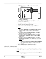
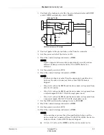
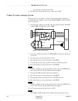
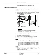
Page 41: ...age 9 2 1 Power Outlet on page 9 3 2 Ground Earth Integrity on page 9 4 3 Ground Earth Wire Leakage Current on page 9 5 4 Enclosure Leakage Current on page 9 6 5 Patient Source Leakage Current on page 9 8 6 Patient Sink Leakage Current on page 9 9 7 Power Cord and Plug on page 9 10 Recommended Tests and Checkout Procedures on page 9 10 1 Power Test on page 9 11 2 Battery Function Test on page 9 12...

Page 42: ...es or other damage Physical damage to a LCD touchscreen face may jeopardize its performance Have the LCD replaced by qualified service personnel if necessary Safety labels and inscription on the device are clearly legible Check for loose or missing screws on the mounting hardware Cleaning Cautions Improper cleaning methods can result in degradation of the equipment performance and or failure To av...

Page 43: ...cotton swab or soft cloth Use compressed air to remove dust from connectors and vents Battery General The lithium ion battery is a rechargeable battery containing lithium ion cells Each battery contains an integrated electronic fuel gauge and a safety protection circuit The processor within the equipment communicates with both the battery and the charger via the SMBUS 2 wire serial interface The f...

Page 44: ...o charger This condition cycle recalibrates the electronic fuel gauge NOTE For clinical use guidelines on charging conditioning or other daily use of batteries refer to the operator s manual Storage Recommendations Store the battery outside of the device at a temperature between 20 to 25 C 68 to 77 F When the battery is stored inside a device that is powered by an AC power source the battery cell ...

Page 45: ... CONDITION LEDs remain illuminated for one minute the battery is awake NOTE You may have to repeat these steps more than once for a battery that has been sleep for a long time 3 Charge the battery Internal GE recommends using the Cadex SMart Two Charger to wake up a battery To wake up a battery inside the monitor follow this procedure 1 Connect the external power supply to the DC power connector o...

Page 46: ...ransport Pro Revision A 2012659 042 Maintenance Repair Log Repair Log Use the repair log to record the repair history of this product Monitor Serial Number Institution Name Date Maintenance Repair Technician ...

Page 47: ...Revision A Transport Pro 6 1 2012659 042 6 Troubleshooting ...

Page 48: ...n Required Tools Equipment Standard set of hand tools Digital multimeter Problems Before starting any detailed troubleshooting complete a thorough visual inspection of the following All cable connections secure Devices properly powered Connected to a proper power source Audible Alarms 1 Press the Silence Alarm Admit key and check for audio feedback 2 If there is audio feedback adjust alarm volume ...

Page 49: ...t board and check resistance on main processor board from J16 pin 1 to ground red and from J16 pin 3 to ground yellow If resistance is less than 10k ohms replace the main processor FRU If equal to or greater than 10k ohms replace the alarm light FRU Display Blank Battery Powered 1 If the control panel lights are off check the battery See Battery Function Test on page 9 12 Replace or recharge as ne...

Page 50: ...lace the main processor FRU If within range replace the inverter FRU Display Dim 1 Clean the display 2 Adjust the brightness 3 Check the voltage between J11 pin 6 and J11 pin 3 on the main processor with brightness set to 100 percent 4 If voltage is greater than 2 3 V replace the inverter board If this does not remedy the problem replace the display FRU If voltage is less than 2 3V replace the mai...

Page 51: ...z During Alarms 1 Reboot the monitor 2 Reseat speaker cable connection 3 Verify that speaker and or cable is not damaged 4 If speaker or cables are damaged replace the speaker FRU 5 Unplug speaker and check speaker cable resistance 6 If resistance is between 6 and 8 ohms replace the main processor FRU 7 If resistance is outside 6 and 8 ohms replace the speaker Always 1 Reboot the monitor 2 Replace...

Page 52: ...tored in Flash is not valid Main Code cannot be loaded until valid Boot Code exists Main Flash test FAILED ERROR The Main Code stored in flash is not valid Static RAM test FAILED ERROR The SRAM memory test failed Main Code will not be loaded unless this test passes Reboot the monitor to repeat testing 1 Power cycle 2 If problems persists replace the main processor FRU Real Time Clock FAILED will n...

Page 53: ...operation The monitor also provides power to a acquisition device via its battery power or external AC power source Service Menu These service menus track and log information that may be helpful for some troubleshooting scenarios WARNING The Boot Loader Service Menu and the Service Mode menu are intended for qualified personnel only It is possible to lose patient data and damage the operating soft...

Page 54: ...ERVICE PORT INTERNET ADDRESS Change the monitor s IP address for software upgrades SET CONFIGURATION Select country not for text translation and language setting for displayed text VIDEO TEST SCREENS Test display s color resolution BATTERY SIMULATION For GE engineering use only WAKE UP BATTERY Wake up a battery OPTIONS MENU Clear the configuration memory erases all patient histories and reset all ...

Page 55: ...IEW INPUT ERRORS Displays time dated input software errors in the Run Time Error Log pop up window 5 Use the TRIM KNOB control to scroll through each logged error The following parameters display for each error Parameter Description PROCESS NAME The task that was operating when the event or problem occurred ERROR CODE A software code for the type of event or problem that occurred SEVERITY Indicate...

Page 56: ...ry Service menu provides you with non real time information about the monitor s internal batteries It does not provide information about connected TRAM batteries 1 Select MORE MENUS MONITOR SETUP 2 Select SERVICE MODE and enter the password 3 Select BATTERY SERVICE NOTE If there is only one internal battery no information will display in the Battery B column ERROR NUMBER A sequential number used t...

Page 57: ...Revision A Transport Pro 7 1 2012659 042 7 Ordering Parts ...

Page 58: ...f you require additional information or troubleshooting assistance contact GE Technical Support To order parts contact Service Parts at the address or telephone number listed on the How to Reach Us page found in the front of this manual For the latest parts information including substitutions obsolescence and compatibility please visit our Parts ID Portal website http egems gehealthcare com partsi...

Page 59: ...Revision A Transport Pro 7 3 2012659 042 Ordering Parts Exploded View Exploded View 622A ...

Page 60: ...PCB subassembly4 4 Includes inverter and inverter harness 2021926 005 Alarm light subassembly5 5 Includes speaker alarm light PCB lense and alarm light cable 2021926 006 ePort flex circuit 2021926 007 Foot and battery doors 2021926 008 Handle 2021926 009 Hardware Hardware on page 7 5 2021926 010 TRAM chute 2021926 011 Item Part Number Bedrail hook mount kit 2007665 002 IV pole mounting kit 2021966...

Page 61: ...M2 X 12 with thread lock PCMCIA 4 411508 007 Hex nut M2 PCMCIA 4 411509 001 Phillips head screw M3 X 4 with thread lock ePort flex circuit to shield 2 ePort flex circuit to back plastic 2 Speaker 4 Inverter 2 Processor PCB 4 14 2000540 007 Phillips head screw M3 X 6 with thread lock LCD mounting brackets 4 Foot 2 6 2000540 001 Phillips head screw M4 X 25 with thread lock Handle 4 2000543 001 Phill...

Page 62: ...7 6 Transport Pro Revision A 2012659 042 Ordering Parts Hardware ...

Page 63: ...Revision A Transport Pro 8 1 2012659 042 8 Disassembly ...

Page 64: ...assembly Assembly Guidelines WARNINGS REPAIR TO THE FRU LEVEL Field repairs are recommended to the field replaceable unit FRU only Attempting a field repair on a PCB or a factory sealed component or assembly could jeopardize the safe and effective operation of the device NOTE GE recommends that you assemble the devices using the NEW screws with a thread lock coating provided in the hardware kit Sc...

Page 65: ...esistant to the ESD damage Discharge any static charge you may have built up before handling semiconductors or assemblies containing semiconductors A grounded antistatic wristband 3M part number 2046 or equivalent or heel strap should be worn AT ALL TIMES while handling or repairing assemblies containing semiconductors Use properly grounded soldering and test equipment Use a static free work surfa...

Page 66: ...e you remove the shipping bracket ALWAYS keep the display on a flat work surface with the TRIM KNOB control hanging over the edge The back plastic is not a FRU However most FRU disassembly assembly instructions require you to remove the back plastic To remove the back plastic follow this procedure 1 Unplug the monitor from the AC power source 2 Remove both batteries from the monitor 3 Remove the T...

Page 67: ... the alarm light cover 7 Disconnect the alarm light cable harness from the alarm light PCB 8 Lay both halves of the monitor on a flat work surface and hang the TRIM KNOB control over the edge of the work surface 9 Disconnect the battery harness from the main processor PCB 625A 626A 627A ...

Page 68: ...ircuit cable to the main processor PCB shield with the two screws PN 402440 002 2 Reconnect the battery harness to the main processor PCB 3 Reconnect the alarm light cable harness to the alarm light PCB 4 Reposition the alarm light cover 5 Secure the back plastic to the front plastic with the six screws PN 402440 002 6 Attach the TRAM chute to the foot with the screw PN 2000546 005 7 Insert the TR...

Page 69: ...c See Back Plastic Replacement on page 8 4 2 Remove the display subassembly a Remove the four screws holding the main processor PCB to the display assembly b Pull out the backlight friction connector from the inverter PCB Do not pull on the connector wires c Squeeze the connector tabs and pull out the connector from the 629A 630A ...

Page 70: ...TRIM KNOB control hanging over the edge of the work surface 3 Remove the two screws from the shipping bracket on the new display Discard the bracket and screws 4 Reinstall the main processor PCB Be sure to reconnect the backlight friction keypad PCB and display friction connectors to the main processor PCB 5 Secure the main processor PCB to the display assembly with the four screws PN 2000540 007 ...

Page 71: ...assembly on page 8 4 2 Remove the seven screws from the battery housing located in the back half of the monitor 3 Remove the battery harness from the back half of the monitor 4 Remove the display subassembly See Display Subassembly on page 8 7 5 Remove the main processor PCB subassembly Follow your country requirements for PCB disposal 636A 637A ...

Page 72: ...n as shown below 7 Install the new main processor PCB subassembly 8 Reinstall the main processor PCB Be sure to reconnect the backlight friction keypad PCB and display friction connectors to the main processor PCB 9 Secure the main processor PCB to the display assembly with the four screws PN 2000540 007 10 Reconnect the battery harness to the display subassembly 11 Secure the battery housing to t...

Page 73: ...plastic 3 Pull out the display friction connector from the main processor PCB 4 Install the new front plastic 5 Reinstall the main processor PCB Be sure to reconnect the backlight friction keypad PCB and display friction connectors to the main processor PCB 6 Secure the main processor PCB to the display assembly with the four screws PN 2000540 007 7 Assemble the back plastic See Back Plastic Assem...

Page 74: ...t the speaker harness from the shield 5 Install the new speaker 6 Connect the speaker harness 7 Secure the speaker to the main processor PCB with the four screws PN 2000540 007 8 Reinstall the main processor PCB Be sure to reconnect the backlight friction keypad PCB and display friction connectors to the main processor PCB 9 Secure the main processor PCB to the display assembly with the four screw...

Page 75: ...ing the inverter board on the shield 4 Remove the backlight friction connector from the main processor PCB 5 Install the new inverter board onto the shield 6 Connect the backlight friction connector 7 Secure the inverter board to the main processor PCB with the two screws PN 2000540 007 8 Reinstall the display subassembly Be sure to reconnect the backlight friction keypad PCB and display friction ...

Page 76: ...assembly on page 8 4 2 Remove the display subassembly See Display Subassembly on page 8 7 3 Disconnect the alarm light cable harness from the alarm light PCB and the main processor PCB 4 Replace the alarm light PCB and alarm light harness 5 Connect the alarm light cable harness to the alarm light PCB and main processor PCB 6 Assemble the back plastic See Back Plastic Assembly on page 8 6 625A ...

Page 77: ...ge 8 4 2 Remove the two screws that connect the flex circuit cable to the main processor PCB shield 3 Remove the battery housing See Main Processor PCB Subassembly on page 8 9 4 Remove the two screws attaching the flex circuit cable to the back plastic 5 Replace the flex circuit 6 Assemble the back plastic See Back Plastic Assembly on page 8 6 628A ...

Page 78: ...2 Disassembly FRU Replacement Foot 1 Remove the two screws that attach the foot to the back plastic 2 Pull to slide the foot out of the grooves in the back plastic 3 Slide the new foot into place and install the two screws PN 2000540 001 603A ...

Page 79: ...embly FRU Replacement Battery Doors 1 Remove the battery door screws and battery doors 2 Insert battery door B into the top position 3 Insert battery door A into the bottom position 4 Insert and tighten the two battery door screws PN 2000905 001 604A ...

Page 80: ...isassembly FRU Replacement Handle 1 Remove the four screws that connect handle to the display 2 Remove the handle 3 Align new handle and press firmly into place You will hear a snap when in place 4 Secure with the four screws PN 2000543 001 603A ...

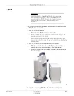
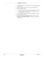
Page 81: ...he TRAM module a Disconnect the TRAM communication cable b Press and hold the release levers simultaneously and pull the module out about 15 cm 6 in c Once released grasp the module firmly with both hands and remove the rest of the way Do not try to hold the module by the release levers 2 Remove the TRAM chute from the back of the display a Tilt the monitor back and use a Phillips head screwdriver...

Page 82: ... Install the TRAM module a Facing the chute guide the back end of the module into the slot b Gently push the module into the chute You will hear a click when the module is fully inserted 7 Insert the TRAM communication cable into Video In connector on the left side of the monitor 8 Insert the other end of the TRAM communication cable into the TRAM module s DISPLAY DISPL connector on the front of t...

Page 83: ...Revision A Transport Pro 9 1 2012659 042 9 Checkout ...

Page 84: ...ING Failure to implement a satisfactory maintenance schedule may cause undue equipment failure and possible health hazards Unless you have an Equipment Maintenance Contract GE does not in any manner assume the responsibility for performing the recommended maintenance procedures The sole responsibility rests with the individual or institution using the equipment GE service personnel may at their di...

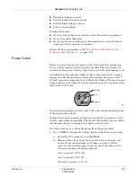
Page 85: ... figure below indicates the location of each on a 120 V AC wall receptacle commonly used in the United States The location and shape of pins may be different on wall receptacles used in countries other than the United States For international power outlets refer to the internal standards agencies of that particular country If other than normal polarity and ground is indicated corrective action mus...

Page 86: ...ine whether the device s exposed metal and power inlet s earth ground connection has a power ground fault condition Perform the test method below that is required by your Country Local governing safety organization NOTE When testing the monitor the device under test includes the optional external power supply Ground Continuity 1 Disconnect the device under test from the power outlet 2 Connect the ...

Page 87: ... determined from the current and voltage drop It shall not exceed the values indicated For equipment without a power supply cord the impedance between the protective earth terminal and the ground tabs of the Video In connector which is protectively earthed shall not exceed 0 1 ohms For equipment with a power supply cord the impedance between the protective earth pin in the mains plug and the groun...

Page 88: ...50 60 Hz 300 µA 0 3 volts on the DMM and the device under test is powered from a centered tapped 200 240 V 50 60 Hz single phase circuit 500 µA 0 5 volts on the DMM and the device under test is powered from a non center tapped 200 240 V 50 60 Hz single phase circuit NOTE Center tapped and non center tapped supply circuits produce different leakage currents and the UL and EN limits are different 7 ...

Page 89: ...the device under test is powered from 100 120 V 50 60 Hz 300 µA 0 3 volts on the DMM and the device under test is powered from a centered tapped 200 240 V 50 60 Hz single phase circuit 500 µA 0 5 volts on the DMM and the device under test is powered from a non center tapped 200 240 V 50 60 Hz single phase circuit 7 Set the GND switch on the leakage tester to CLOSED 8 Read the current leakage indic...

Page 90: ...5 Change the leakage tester polarity switch to the RVS position 6 Read the leakage current indicated on the DMM NOTE If either reading is greater than 50 µA 0 05 volts on the DMM the device fails this test Contact GE Technical Support 7 Change the GND switch to the Closed position 8 Read the leakage current indicated on the DMM 9 Change the leakage current switch to the RVS position 10 Read the le...

Page 91: ...ester polarity switch to the RVS position 5 Read the leakage current indicated on the DMM NOTE If either reading is greater than the appropriate specification below the device under test fails Contact GE Technical Support 10 µA 0 01 volts on the DMM at 120 V AC using the test body 20 µA 0 02 volts on the DMM at 240 V AC using the test body 50 µA 0 05 volts on the DMM at 120 240 V AC using the ECG ...

Page 92: ...ckout Procedures After re assembling the monitor ALWAYS complete the checkout procedures electrical safety tests and regular maintenance procedures identified and described in this manual Recommended Electrical Safety Tests and Checkout Procedures Replacement or Upgrade Checkout Procedures Electrical Safety Tests Display 1 Power Test on page 9 11 2 Battery Function Test on page 9 12 3 Video Test S...

Page 93: ...ntrol panel indicators illuminate on power up 5 Verify the DC power indicator on the monitor stays illuminated NOTE If the DC power indicator stays on but the display is blank the monitor is likely in standby mode battery charging Press and hold the Power button for approximately 0 25 seconds to enter the normal mode If the DC power indicator is on continue with the tests If either of the Charging...

Page 94: ...Battery Function Test The battery application software will behave differently depending on whether a acquisition device is connected This fact also applies to which device was the last device that was connected Throughout this document when reference is made to a device being connected this also applies to the device being connected and then disconnected without a different device being connected...

Page 95: ...to 10 Reset the brightness level to your default setting Speaker Test 1 Select MORE MENUS ALARM CONTROL ALARM VOL 2 Change the alarm volume to 100 3 Verify the speaker volume changes accordingly 4 Return the volume to the level it was previously set to before you changed it for this test TRAM Communication Test 1 Confirm that all components of the monitoring system are correctly connected as descr...

Page 96: ... to service Complete a PM Form and Repair Log PM Form If repairs adjustments were made or any parts replaced describe this in the area provided on the PM form Also include comments regarding any unusual environmental conditions that may affect the operation or reliability of the equipment in the area provided on the PM form For the latest PM form for this product contact GE Service ...

Page 97: ...Revision A Transport Pro A 1 2012659 042 A Technical Specifications ...

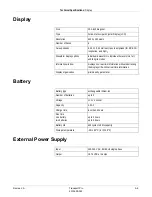
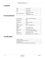
Page 98: ...ith TRAM 15 W 60 W Power dissipation 120 Btu Hour maximum Cooling passive Atmospheric pressure 425 817 mmHg 56 109 kPa Temperature operating storage 10 to 40 C 50 to 104 F 40 to 70 C 40 to 158 F Relative humidity 5 to 95 at 40 C non condensing Vibration MIL STD 810E Method 514 4 Category 1 Fluid ingress test Meets EN 60601 2 27 IPX0 Drop test standard Meets EN 60601 1 from 76 2 cm 30 inches UL 606...

Page 99: ...ndividual 3 waveforms full and full grid modes Information window displays non real time information without obstructing the display of life critical real time information Display organization prioritized by parameter Battery type exchangeable lithium ion Number of batteries up to 2 Voltage 11 1 V nominal Capacity 3 9 Ah Charge time less than 4 hours Run time one battery two batteries up to 2 hour...

Page 100: ...A 4 Transport Pro Revision A 2012659 042 Technical Specifications External Power Supply ...

Page 101: ...Revision A Transport Pro B 1 2012659 042 B Electromagnetic Compatibility ...

Page 102: ...tested to verify normal operation in the configuration in which it is being used Guidance and Manufacturer s Declaration Electromagnetic Emissions The Transport Pro system is intended for use in the electromagnetic environment specified below It is the responsibility of the customer or user to assure that the system is used in such an environment Emissions Test Compliance Electromagnetic Environme...

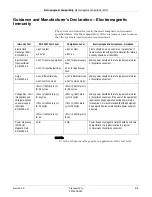
Page 103: ...al commercial or hospital environment 1 kV for input output lines 1 kV for input output lines Surge EN 61000 4 5 1 kV differential mode 1 kV differential mode Mains power should be that of a typical commercial or hospital environment 2 kV common mode 2 kV common mode 5 Ut 95 dip in Ut for 0 5 cycles 5 Ut 95 dip in Ut for 0 5 cycles Voltage dips short interruptions and voltage variations on power s...

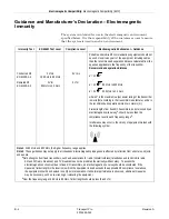
Page 104: ... separation distance in meters m Field strengths from fixed RF transmitters as determined by an electromagnetic site surveya should be less than the compliance level in each frequency rangeb Interference may occur in the vicinity of equipment marked with the following symbol Note 1 At 80 MHz and 800 MHz the higher frequency range applies Note 2 These guidelines may not apply in all situations Elec...

Page 105: ...mmunications equipment For transmitters rated at a maximum output power not listed above the recommended separation distance d in meters m can be estimated using the equitation applicable to the frequency of the transmitter where P is the maximum output power rating of the transmitter in watts W according to the transmitter manufacturer NOTE These guidelines may not apply in all instances Electrom...

Page 106: ...00X Multi Link 3 5 Ld ECG Cable 3 6 m 12 ft 2017004 00X Multi Link 3 Ld Neonatal ECG Cable 3 6 m 12 ft 2021141 00X Multi Link 3 Ld ECG Cable w Grabber 3 6 m 12 ft 2017005 00X Multi Link 6 Ld ECG Cable 3 6 m 12 ft 2017006 00X Multi Link 10 Ld ECG Cable 3 6 m 12 ft 2017007 001 Multi Link 3 5 6 Adapter N A M1020453 M1020454 Multi Link to 300 Series 3 Ld Trunk Cable 3 0 m 10 ft M1020541 M1020546 Multi...

Page 107: ...aps 75 cm 30 in 545316 535318 300 Series 5 Ld Set w clips 125 cm 49 in 8001959 8001961 300 Series 5 Ld Set w clips 1 5 m 60 in 545328 300 Series 5 Ld Set w snaps 125 cm 49 in 54534X 300 Series replacement clip lead 125 cm 49 in 800327X 300 Series replacement clip lead 1 5 m 60 in 545358 545359 300 Series replacement clip lead 75 cm 30 in 54535X 300 Series replacement snap lead 125 cm 49 in Invasiv...

Page 108: ...e Cable 3 6 m 12 ft 2002592 00X Masimo Set Interface Cable 3 6 m 12 ft 2017002 00X Masimo Set Interface Cable 3 6 m 12 ft 2002799 001 Masimo Finger Sensor Pediatric N A 2002800 001 Masimo Finger Sensor Adult N A 407705 00X Nellcor Sensor Finger Probe N A Accessories 2006171 00X TRAM Module Series N A 403496 001 TRAM Communication Cable 4 5 m 15 ft N A RJ45 series Category 5 cable N A 2017857 002 B...

Page 109: ......
Page 110: ...esentative GE Medical Systems Information Technologies GmbH Munzinger Straße 3 5 D 79111 Freiburg Germany Tel 49 761 45 43 0 Fax 49 761 45 43 233 Asia Headquarters GE Medical Systems Information Technologies Asia GE China Co Ltd 24th Floor Shanghai MAXDO Center 8 Xing Yi Road Hong Qiao Development Zone Shanghai 200336 P R China Tel 86 21 5257 4650 Fax 86 21 5208 2008 0459 gemedical com ...

Reviews: