GE Multilin
F35 Multiple Feeder Protection System
5-115
5 SETTINGS
5.4 SYSTEM SETUP
5
The relay using a given FlexCurve applies linear approximation for times between the user-entered points. Special
care must be applied when setting the two points that are close to the multiple of pickup of 1; that is, 0.98 pu and
1.03 pu. It is recommended to set the two times to a similar value; otherwise, the linear approximation may result in
undesired behavior for the operating quantity that is close to 1.00 pu.
b) FLEXCURVE CONFIGURATION WITH ENERVISTA UR SETUP
The EnerVista UR Setup software allows for easy configuration and management of FlexCurves and their associated data
points. Prospective FlexCurves can be configured from a selection of standard curves to provide the best approximate fit,
then specific data points can be edited afterwards. Alternately, curve data can be imported from a specified file (.csv format)
by selecting the
Import Data From
EnerVista UR Setup setting.
Curves and data can be exported, viewed, and cleared by clicking the appropriate buttons. FlexCurves are customized by
editing the operating time (ms) values at pre-defined per-unit current multiples. Note that the pickup multiples start at zero
(implying the "reset time"), operating time below pickup, and operating time above pickup.
c) RECLOSER CURVE EDITING
Recloser curve selection is special in that recloser curves can be shaped into a composite curve with a minimum response
time and a fixed time above a specified pickup multiples. There are 41 recloser curve types supported. These definite oper-
ating times are useful to coordinate operating times, typically at higher currents and where upstream and downstream pro-
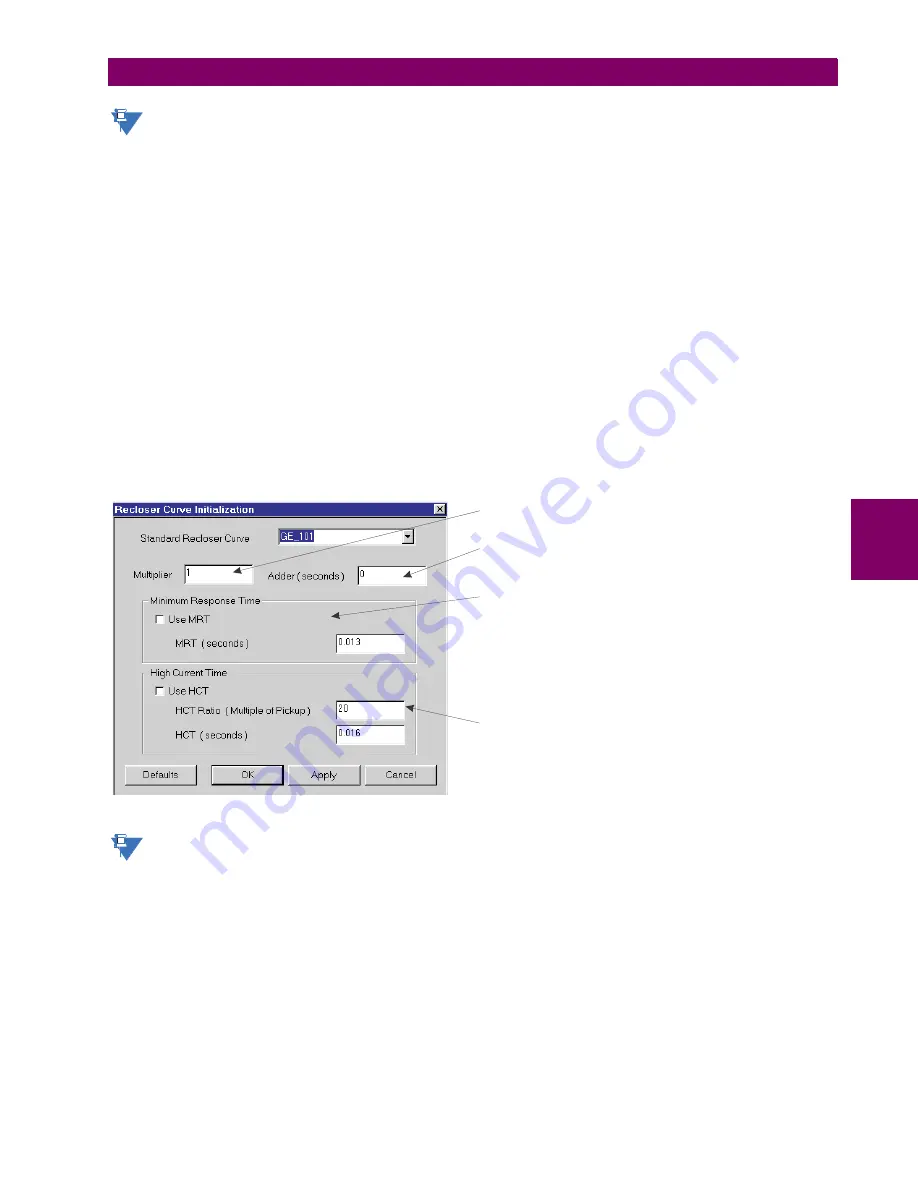
tective devices have different operating characteristics. The recloser curve configuration window shown below appears
when the Initialize From EnerVista UR Setup setting is set to “Recloser Curve” and the
Initialize FlexCurve
button is
clicked.
Figure 5–30: RECLOSER CURVE INITIALIZATION
The multiplier and adder settings only affect the curve portion of the characteristic and not the MRT and HCT set-
tings. The HCT settings override the MRT settings for multiples of pickup greater than the HCT ratio.
NOTE
842721A1.CDR
Multiplier:
Scales (multiplies) the curve operating times
Addr:
Adds the time specified in this field (in ms) to each
operating time value.
curve
Minimum Response Time (MRT):
If enabled, the MRT setting
defines the shortest operating time even if the curve suggests
a shorter time at higher current multiples. A composite operating
characteristic is effectively defined. For current multiples lower
than the intersection point, the curve dictates the operating time;
otherwise, the MRT does. An information message appears
when attempting to apply an MRT shorter than the minimum
curve time.
High Current Time:
HCT Ratio
HCT
Allows the user to set a pickup multiple
from which point onwards the operating time is fixed. This is
normally only required at higher current levels. The
defines the high current pickup multiple; the
defines the
operating time.
NOTE
Summary of Contents for UR F35 Series
Page 10: ...x F35 Multiple Feeder Protection System GE Multilin TABLE OF CONTENTS ...
Page 366: ...5 238 F35 Multiple Feeder Protection System GE Multilin 5 10 TESTING 5 SETTINGS 5 ...
Page 426: ...10 12 F35 Multiple Feeder Protection System GE Multilin 10 6 DISPOSAL 10 MAINTENANCE 10 ...
Page 454: ...A 28 F35 Multiple Feeder Protection System GE Multilin A 1 PARAMETER LISTS APPENDIX A A ...
Page 620: ...F 12 F35 Multiple Feeder Protection System GE Multilin F 2 DNP POINT LISTS APPENDIX F F ...
Page 630: ...H 8 F35 Multiple Feeder Protection System GE Multilin H 3 WARRANTY APPENDIX H H ...
Page 640: ...x F35 Multiple Feeder Protection System GE Multilin INDEX ...


