GE Multilin
C70 Capacitor Bank Protection and Control System
2-5
2 PRODUCT DESCRIPTION
2.1 INTRODUCTION
2
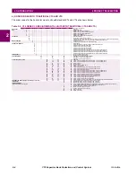
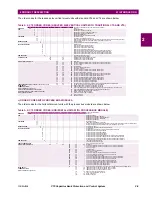
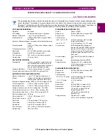
The order codes for the reduced size vertical mount units with standard CTs and VTs are shown below.
c) ORDER CODES WITH PROCESS BUS MODULES
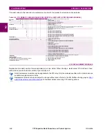
The order codes for the horizontal mount units with the process bus module are shown below.
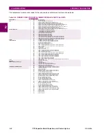
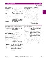
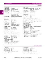
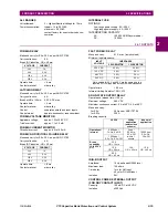
Table 2–4: C70 ORDER CODES (REDUCED SIZE VERTICAL UNITS WITH TRADITIONAL CTS AND VTS)
C70
-
*
**
-
*
*
*
- F
**
- H
**
- M
**
-
P/R
**
Reduced Size Vertical Mount (see note regarding P/R slot below)
BASE UNIT
C70
|
|
|
|
|
|
|
|
|
Base Unit
CPU
E
|
|
|
|
|
|
|
|
RS485 and RS485
G
|
|
|
|
|
|
|
|
RS485 and multi-mode ST 10Base-F
H
|
|
|
|
|
|
|
|
RS485 and multi-mode ST redundant 10Base-F
J
|
|
|
|
|
|
|
|
RS485 and multi-mode ST 100Base-FX
N
|
|
|
|
|
|
|
|
RS485 and 10/100Base-T
S
|
|
|
|
|
|
|
|
RS485 and managed six-port Ethernet switch
SOFTWARE
00
|
|
|
|
|
|
|
No software options
03
|
|
|
|
|
|
|
IEC 61850; not available for type E CPUs
12
|
|
|
|
|
|
|
Enhanced capacitor bank control (time and date, capacitor control supervision, automatic voltage regulator)
13
|
|
|
|
|
|
|
Enhanced capacitor bank control and IEC 61850; not available for type E CPUs
MOUNT/COATING
V
|
|
|
|
|
|
Vertical (3/4 rack)
B
|
|
|
|
|
|
Vertical (3/4 rack) with harsh environmental coating
FACEPLATE/ DISPLAY
C
|
|
|
|
|
English display
K
|
|
|
|
|
Enhanced front panel with English display
M
|
|
|
|
|
Enhanced front panel with French display
Q
|
|
|
|
|
Enhanced front panel with Russian display
U
|
|
|
|
|
Enhanced front panel with Chinese display
L
|
|
|
|
|
Enhanced front panel with English display and user-programmable pushbuttons
N
|
|
|
|
|
Enhanced front panel with French display and user-programmable pushbuttons
T
|
|
|
|
|
Enhanced front panel with Russian display and user-programmable pushbuttons
V
|
|
|
|
|
Enhanced front panel with Chinese display and user-programmable pushbuttons
POWER SUPPLY
H
|
|
|
|
125 / 250 V AC/DC power supply
L
|
|
|
|
24 to 48 V (DC only) power supply
CT/VT MODULES
8L
|
8L
|
Standard 4CT/4VT with enhanced diagnostics
8N
|
8N
|
Standard 8CT with enhanced diagnostics
8V
|
8V
|
Standard 8VT with enhanced diagnostics
DIGITAL INPUTS/OUTPUTS
XX
XX
No Module
6A
6A
6A
2 Form-A (voltage with optional current) and 2 Form-C outputs, 8 digital inputs
6B
6B
6B
2 Form-A (voltage with optional current) and 4 Form-C outputs, 4 digital inputs
6C
6C
6C
8 Form-C outputs
6D
6D
6D
16 digital inputs
6E
6E
6E
4 Form-C outputs, 8 digital inputs
6F
6F
6F
8 Fast Form-C outputs
6G
6G
6G
4 Form-A (voltage with optional current) outputs, 8 digital inputs
6H
6H
6H
6 Form-A (voltage with optional current) outputs, 4 digital inputs
6K
6K
6K
4 Form-C and 4 Fast Form-C outputs
6L
6L
6L
2 Form-A (current with optional voltage) and 2 Form-C outputs, 8 digital inputs
6M
6M
6M
2 Form-A (current with optional voltage) and 4 Form-C outputs, 4 digital inputs
6N
6N
6N
4 Form-A (current with optional voltage) outputs, 8 digital inputs
6P
6P
6P
6 Form-A (current with optional voltage) outputs, 4 digital inputs
6R
6R
6R
2 Form-A (no monitoring) and 2 Form-C outputs, 8 digital inputs
6S
6S
6S
2 Form-A (no monitoring) and 4 Form-C outputs, 4 digital inputs
6T
6T
6T
4 Form-A (no monitoring) outputs, 8 digital inputs
6U
6U
6U
6 Form-A (no monitoring) outputs, 4 digital inputs
6V
6V
6V
2 Form-A outputs, 1 Form-C output, 2 Form-A (no monitoring) latching outputs, 8 digital inputs
TRANSDUCER INPUTS/OUTPUTS (maximum of 3 per unit)
5A
5A
5A
4 dcmA inputs, 4 dcmA outputs (only one 5A module is allowed)
INTER-RELAY
COMMUNICATIONS
(select a maximum of 1 per unit)
For the last module, slot P is used for digital
input/output modules; slot R is used for inter-relay
communications modules.
2G
IEEE C37.94, 820 nm, 128 kbps, multimode, LED, 1 Channel
2H
IEEE C37.94, 820 nm, 128 kbps, multimode, LED, 2 Channels
2S
Six-port managed Ethernet switch with high voltage power supply (110 to 250 V DC / 100 to 240 V AC)
2T
Six-port managed Ethernet switch with low voltage power supply (48 V DC)
77
IEEE C37.94, 820 nm, multimode, LED, 2 Channels
7H
820 nm, multi-mode, LED, 2 Channels
7I
1300 nm, multi-mode, LED, 2 Channels
7S
G.703, 2 Channels
7W
RS422, 2 Channels
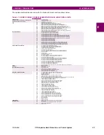
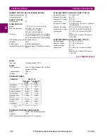
Table 2–5: C70 ORDER CODES (HORIZONTAL UNITS WITH PROCESS BUS MODULE)
C70
-
*
**
-
*
*
*
- F
**
- H
**
- M
**
- P
**
- U
**
-
W/X
**
Full Size Horizontal Mount
BASE UNIT
C70
|
|
|
|
|
|
|
|
|
|
|
Base Unit
CPU
E
|
|
|
|
|
|
|
|
|
|
RS485 and RS485
G
|
|
|
|
|
|
|
|
|
|
RS485 and multi-mode ST 10Base-F
H
|
|
|
|
|
|
|
|
|
|
RS485 and multi-mode ST redundant 10Base-F
J
|
|
|
|
|
|
|
|
|
|
RS485 and multi-mode ST 100Base-FX
N
|
|
|
|
|
|
|
|
|
|
RS485 and 10/100Base-T
SOFTWARE
00
|
|
|
|
|
|
|
|
|
No software options
03
|
|
|
|
|
|
|
|
|
IEC 61850; not available for type E CPUs
12
|
|
|
|
|
|
|
|
|
Enhanced capacitor bank control (time and date, capacitor control supervision, automatic voltage regulator)
13
|
|
|
|
|
|
|
|
|
Enhanced capacitor bank control and IEC 61850; not available for type E CPUs
MOUNT/COATING
H
|
|
|
|
|
|
|
|
Horizontal (19” rack)
A
|
|
|
|
|
|
|
|
Horizontal (19” rack) with harsh environmental coating
FACEPLATE/ DISPLAY
C
|
|
|
|
|
|
|
English display
P
|
|
|
|
|
|
|
English display with 4 small and 12 large programmable pushbuttons
K
|
|
|
|
|
|
|
Enhanced front panel with English display
M
|
|
|
|
|
|
|
Enhanced front panel with French display
Q
|
|
|
|
|
|
|
Enhanced front panel with Russian display
U
|
|
|
|
|
|
|
Enhanced front panel with Chinese display
L
|
|
|
|
|
|
|
Enhanced front panel with English display and user-programmable pushbuttons
N
|
|
|
|
|
|
|
Enhanced front panel with French display and user-programmable pushbuttons
T
|
|
|
|
|
|
|
Enhanced front panel with Russian display and user-programmable pushbuttons
V
|
|
|
|
|
|
|
Enhanced front panel with Chinese display and user-programmable pushbuttons
POWER SUPPLY
H
|
|
|
|
|
|
125 / 250 V AC/DC power supply
L
|
|
|
|
|
|
24 to 48 V (DC only) power supply
PROCESS BUS MODULE
|
81
|
|
|
|
Eight-port digital process bus module
DIGITAL INPUTS/OUTPUTS
XX
XX
XX
XX
XX
No Module
6A
6A
|
2 Form-A (voltage with optional current) and 2 Form-C outputs, 8 digital inputs
6B
6B
|
2 Form-A (voltage with optional current) and 4 Form-C outputs, 4 digital inputs
6C
6C
|
8 Form-C outputs
6D
6D
|
16 digital inputs
6E
6E
|
4 Form-C outputs, 8 digital inputs
6F
6F
|
8 Fast Form-C outputs
6G
6G
|
4 Form-A (voltage with optional current) outputs, 8 digital inputs
6H
6H
|
6 Form-A (voltage with optional current) outputs, 4 digital inputs
6K
6K
|
4 Form-C and 4 Fast Form-C outputs
6L
6L
|
2 Form-A (current with optional voltage) and 2 Form-C outputs, 8 digital inputs
6M
6M
|
2 Form-A (current with optional voltage) and 4 Form-C outputs, 4 digital inputs
6N
6N
|
4 Form-A (current with optional voltage) outputs, 8 digital inputs
6P
6P
|
6 Form-A (current with optional voltage) outputs, 4 digital inputs
6R
6R
|
2 Form-A (no monitoring) and 2 Form-C outputs, 8 digital inputs
6S
6S
|
2 Form-A (no monitoring) and 4 Form-C outputs, 4 digital inputs
6T
6T
|
4 Form-A (no monitoring) outputs, 8 digital inputs
6U
6U
|
6 Form-A (no monitoring) outputs, 4 digital inputs
6V
6V
|
2 Form-A outputs, 1 Form-C output, 2 Form-A (no monitoring) latching outputs, 8 digital inputs
INTER-RELAY
COMMUNICATIONS
(select a maximum of 1 per unit)
2G
2G
IEEE C37.94, 820 nm, 128 kbps, multimode, LED, 1 Channel
2H
2H
IEEE C37.94, 820 nm, 128 kbps, multimode, LED, 2 Channels
77
77
IEEE C37.94, 820 nm, multimode, LED, 2 Channels
7H
7H
820 nm, multi-mode, LED, 2 Channels
7I
7I
1300 nm, multi-mode, LED, 2 Channels
7S
7S
G.703, 2 Channels
7W
7W
RS422, 2 Channels
Summary of Contents for UR Series C70
Page 2: ......
Page 10: ...x C70 Capacitor Bank Protection and Control System GE Multilin TABLE OF CONTENTS ...
Page 344: ...5 220 C70 Capacitor Bank Protection and Control System GE Multilin 5 10 TESTING 5 SETTINGS 5 ...
Page 586: ...D 10 C70 Capacitor Bank Protection and Control System GE Multilin D 1 OVERVIEW APPENDIXD D ...

