9-16
C70 Capacitor Bank Protection and Control System
GE Multilin
9.1 OVERVIEW
9 THEORY OF OPERATION
9
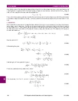
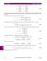
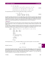
(EQ 9.68)
Note that under external fault conditions, sensitivity may be much different from the non-fault sensitivity.
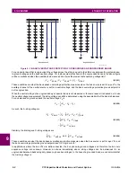
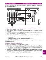
d) RESTRAINT
Severe system voltage unbalance, such as can occur during near-by bolted ground faults, can exacerbate measurement
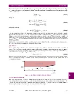
error, resulting in spurious operating signal. To prevent operation under these conditions, percent restraint supervision is
applied using a restraint signal that is the magnitude of the zero-sequence current
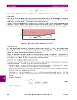
Typically few percent of slope is enough to ensure security of the function. The factor compensating for the inherent bank
unbalance zeroes out the operating signal under relatively balanced bank currents. If the said currents contain a significant
zero sequence component, the quality of compensation is lower, hence the need for the restraint, and this slope setting.
Figure 9–7: NEUTRAL CURRENT UNBALANCE RESTRAINT
e) AUTO-SETTING
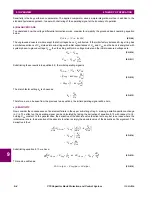
As a convenient alternative to manually determining the unbalance
k
-factor settings, the relay can automatically calculate
these settings from its own measurements while the capacitor is in-service, as described in the
Commands
chapter. The
technique the relay uses is to set the operate signal variable to zero in equation 8.54 and solve for the unbalance factor
k
1
using the average of several successive measurements of the currents.
However, the assumption made here is that when the auto-set command is executed, the capacitor is in an acceptably bal-
anced state, wherein the operating signal ought to be zero. Following the auto-set command, the protection will be measur-
ing changes from the state that existed at the time the auto-set command executed.
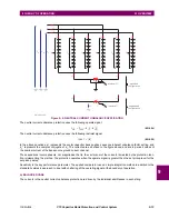
f) APPLICATION TO UNGROUNDED CAPACITOR BANKS
The forgoing discussion of the neutral current balance protection applied to the ground configuration. When applied to
ungrounded configurations, all of the above applies, with the following exceptions:
•
The phase voltages in equations 8.54 through 8.59 must have the neutral voltage
V
X
subtracted. However, as these
voltages are eventually eliminated from the calculations, the outcome is unaffected.
•
A low ratio CT can be used for ungrounded-wye configurations in place of a window type CT as there is no requirement
to form the difference of the primary neutral currents.
•
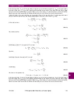
Whereas with the grounded configuration
I
DIF
=
I
N
1
–
I
N
2
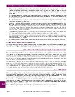
, with the ungrounded configuration
I
DIF
=
I
N
1
= –
I
N
2
. This
results in the –
C
A
2
, –
C
B
2
, and –
C
C
2
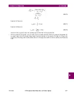
terms disappearing from equations 8.58 through 8.65. This results in the following
changes.
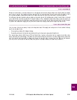
Equation 8.64 becomes:
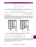
(EQ 9.69)
Equation 8.65 becomes:
I
OP
pu
(
)
I
rated
2
I
base
----------------
C
pu
(
)
Δ
×
=
834749A1.CDR
I
0
I
OP
NTRL CUR PKP
Slope settin
g
Pickup
setting
NTRL CUR DPO
k
1
k
A
a
ˆ
2
k
B
a
ˆ
k
C
+
+
=
C
A
1
C
A
1
C
A
2
+
---------------------------
a
ˆ
2
C
B
1
C
B
1
C
B
2
+
---------------------------
a
ˆ
C
C
1
C
C
1
C
C
2
+
---------------------------
+
+
=
Summary of Contents for UR Series C70
Page 2: ......
Page 10: ...x C70 Capacitor Bank Protection and Control System GE Multilin TABLE OF CONTENTS ...
Page 344: ...5 220 C70 Capacitor Bank Protection and Control System GE Multilin 5 10 TESTING 5 SETTINGS 5 ...
Page 586: ...D 10 C70 Capacitor Bank Protection and Control System GE Multilin D 1 OVERVIEW APPENDIXD D ...

