GE Multilin
C70 Capacitor Bank Protection and Control System
C-19
APPENDIX C
C.5 IEC 61850 IMPLEMENTATION VIA ENERVISTA UR SETUP
C
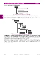
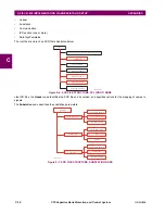
The
Communication
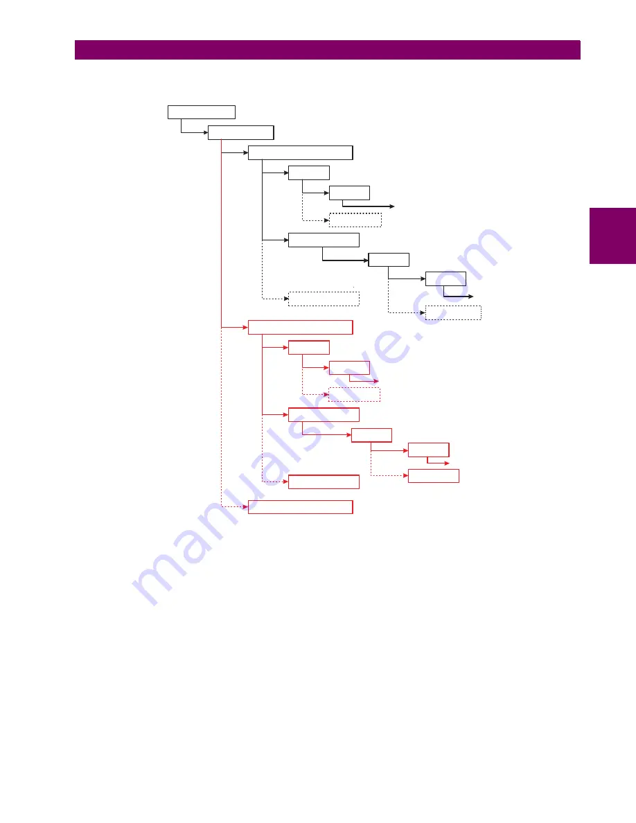
node describes the direct communication connection possibilities between logical nodes by means of
logical buses (sub-networks) and IED access ports. The communication section is structured as follows.
Figure 0–8: SCD FILE STRUCTURE, COMMUNICATIONS NODE
The
SubNetwork
node contains all access points which can (logically) communicate with the sub-network protocol and
without the intervening router. The
ConnectedAP
node describes the IED access point connected to this sub-network. The
Address
node contains the address parameters of the access point. The
GSE
node provides the address element for stat-
ing the control block related address parameters, where
IdInst
is the instance identification of the logical device within the
IED on which the control block is located, and
cbName
is the name of the control block.
842793A1.CDR
Communication
SubNetwork (name)
ConnectedAP (IED 1)
Address
GSE (IdInst, cbName)
P (type)
Other P elements
Text
Address
P (type)
Other P elements
Text
Other GSE elements
ConnectedAP (IED 2)
Address
GSE (IdInst, cbName)
P (type)
Other P elements
Text
Address
P (type)
Text
Other GSE elements
Other ConnectedAP elements
Other P elements
Summary of Contents for UR Series C70
Page 2: ......
Page 10: ...x C70 Capacitor Bank Protection and Control System GE Multilin TABLE OF CONTENTS ...
Page 344: ...5 220 C70 Capacitor Bank Protection and Control System GE Multilin 5 10 TESTING 5 SETTINGS 5 ...
Page 586: ...D 10 C70 Capacitor Bank Protection and Control System GE Multilin D 1 OVERVIEW APPENDIXD D ...

