GE Multilin
C70 Capacitor Bank Protection and Control System
6-9
6 ACTUAL VALUES
6.3 METERING
6
6.3METERING
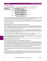
6.3.1 METERING CONVENTIONS
a) UR CONVENTION FOR MEASURING POWER AND ENERGY
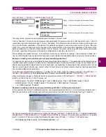
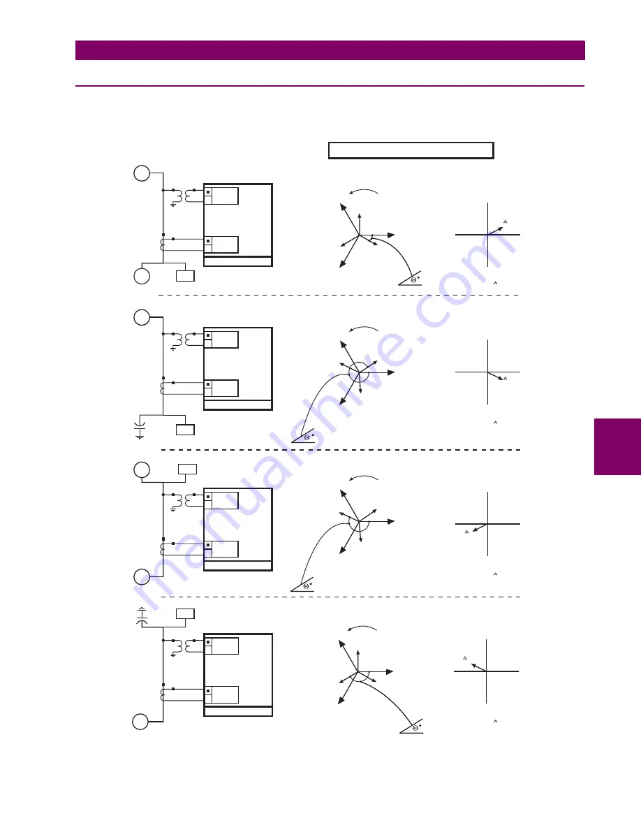
The following figure illustrates the conventions established for use in UR-series relays.
Figure 6–1: FLOW DIRECTION OF SIGNED VALUES FOR WATTS AND VARS
827239AC.CDR
PER IEEE CONVENTIONS
PARAMETERS AS SEEN
BY THE UR RELAY
Voltage
WATTS = Positive
VARS = Positive
PF = Lag
Current
Voltage
WATTS = Positive
VARS = Negative
PF = Lead
Current
Voltage
WATTS = Negative
VARS = Negative
PF = Lag
Current
Voltage
WATTS = Negative
VARS = Positive
PF = Lead
Current
Generator
Generator
Inductive
Inductive
Resistive
Resistive
Generator
Generator
UR RELAY
UR RELAY
UR RELAY
UR RELAY
G
G
M
M
G
G
VCG
IC
VAG
IA
VBG
IB
1
-
VCG
IC
VAG
IA
VBG
IB
2
-
VCG
IC
VAG
IA
VBG
IB
3
-
VCG
IC
VAG
IA
VBG
IB
4
-
+Q
+Q
+Q
+Q
P
F =
Lead
P
F =
Lead
P
F =
Lead
P
F =
Lead
P
F =
Lag
P
F =
Lag
P
F =
Lag
P
F =
Lag
P
F =
Lag
P
F =
Lag
P
F =
Lag
P
F =
Lag
P
F =
Lead
P
F =
Lead
P
F =
Lead
P
F =
Lead
-Q
-Q
-Q
-Q
-P
-P
-P
-P
+P
+P
+P
+P
IA
IA
IA
IA
S=VI
S=VI
S=VI
S=VI
LOAD
LOAD
Resistive
Resistive
LOAD
LOAD
Summary of Contents for UR Series C70
Page 2: ......
Page 10: ...x C70 Capacitor Bank Protection and Control System GE Multilin TABLE OF CONTENTS ...
Page 344: ...5 220 C70 Capacitor Bank Protection and Control System GE Multilin 5 10 TESTING 5 SETTINGS 5 ...
Page 586: ...D 10 C70 Capacitor Bank Protection and Control System GE Multilin D 1 OVERVIEW APPENDIXD D ...

