3-34
C70 Capacitor Bank Protection and Control System
GE Multilin
3.3 DIRECT INPUT/OUTPUT COMMUNICATIONS
3 HARDWARE
3
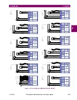
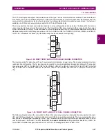
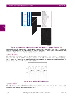
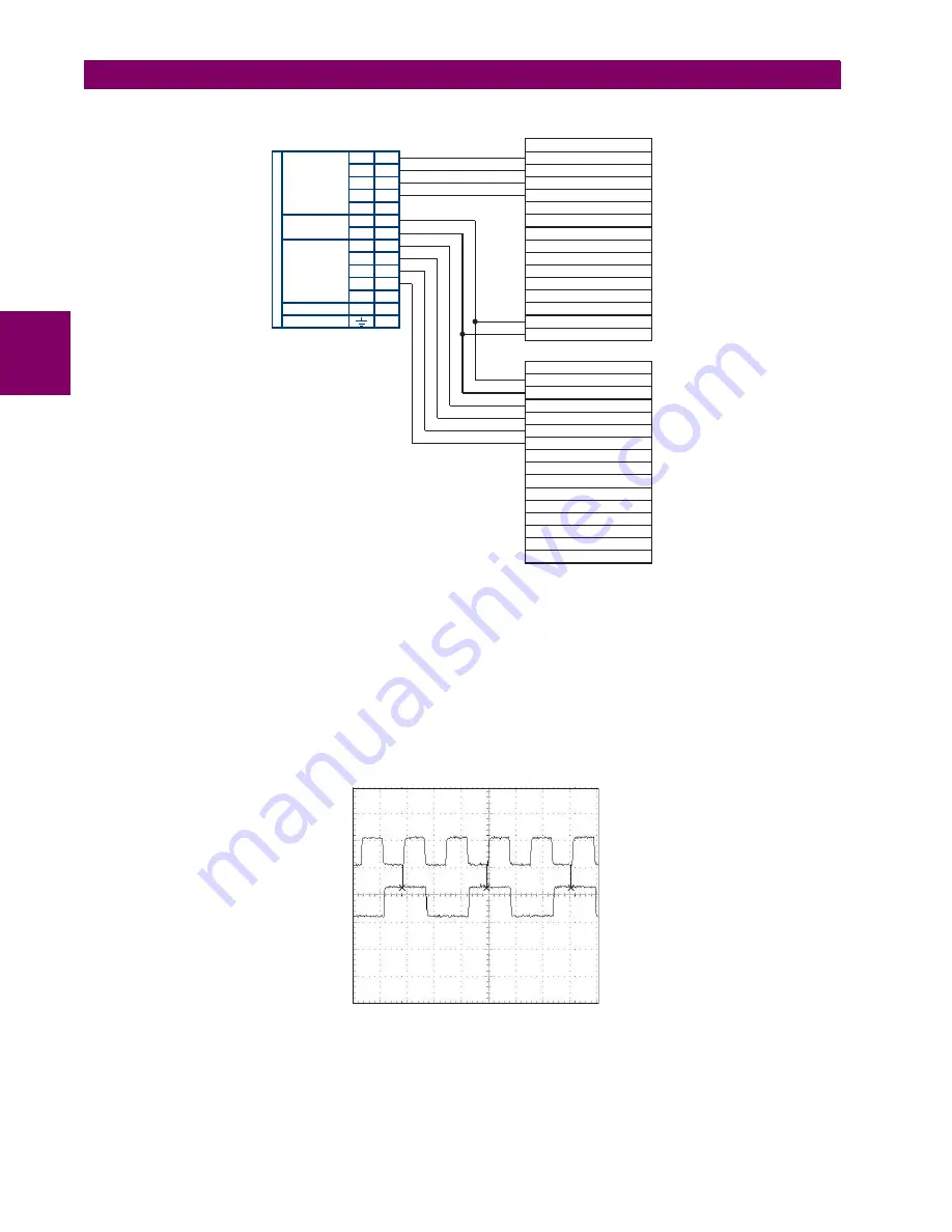
Figure 3–39: TIMING CONFIGURATION FOR RS422 TWO-CHANNEL, 3-TERMINAL APPLICATION
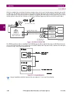
Data module 1 provides timing to the C70 RS422 interface via the ST(A) and ST(B) outputs. Data module 1 also provides
timing to data module 2 TT(A) and TT(B) inputs via the ST(A) and AT(B) outputs. The data module pin numbers have been
omitted in the figure above since they may vary depending on the manufacturer.
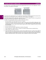
c) TRANSMIT TIMING
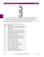
The RS422 interface accepts one clock input for transmit timing. It is important that the rising edge of the 64 kHz transmit
timing clock of the multiplexer interface is sampling the data in the center of the transmit data window. Therefore, it is impor-
tant to confirm clock and data transitions to ensure proper system operation. For example, the following figure shows the
positive edge of the Tx clock in the center of the Tx data bit.
Figure 3–40: CLOCK AND DATA TRANSITIONS
d) RECEIVE TIMING
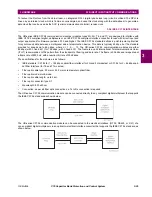
The RS422 interface utilizes NRZI-MARK modulation code and; therefore, does not rely on an Rx clock to recapture data.
NRZI-MARK is an edge-type, invertible, self-clocking code.
Data module 1
Data module 2
Signal name
Signal name
SD(A) - Send data
TT(A) - Terminal timing
TT(B) - Terminal timing
SD(B) - Send data
RD(A) - Received data
RD(A) - Received data
SD(A) - Send data
SD(B) - Send data
RD(B) - Received data
RD(B) - Received data
RS(A) - Request to send (RTS)
RS(A) - Request to send (RTS)
RT(A) - Receive timing
CS(A) - Clear To send
CS(A) - Clear To send
RT(B) - Receive timing
CS(B) - Clear To send
CS(B) - Clear To send
Local loopback
Local loopback
Remote loopback
Remote loopback
Signal ground
Signal ground
ST(A) - Send timing
ST(A) - Send timing
ST(B) - Send timing
ST(B) - Send timing
RS(B) - Request to send (RTS)
RS(B) - Request to send (RTS)
831022A3.CDR
W 7a
W 2b
W 8a
7W
Shld.
Shld.
Tx1(+)
Tx2(+)
Tx1(-)
Tx2(-)
Rx1(+)
Rx2(+)
+
com
Rx1(-)
Rx2(-)
–
INTER-REL
A
Y
C
OMMUNICA
TIONS
W 3a
W 5b
W 5a
W 3b
W 2a
W 6a
W 6b
W 7b
W 8b
W 4b
W 4a
RS422
CHANNEL 1
RS422
CHANNEL 2
CLOCK
SURGE
Tx Clock
Tx Data
Summary of Contents for UR Series C70
Page 2: ......
Page 10: ...x C70 Capacitor Bank Protection and Control System GE Multilin TABLE OF CONTENTS ...
Page 344: ...5 220 C70 Capacitor Bank Protection and Control System GE Multilin 5 10 TESTING 5 SETTINGS 5 ...
Page 586: ...D 10 C70 Capacitor Bank Protection and Control System GE Multilin D 1 OVERVIEW APPENDIXD D ...


