GE Multilin
L90 Line Current Differential System
5-23
5 SETTINGS
5.2 PRODUCT SETUP
5
Multiple LANS, with Redundancy
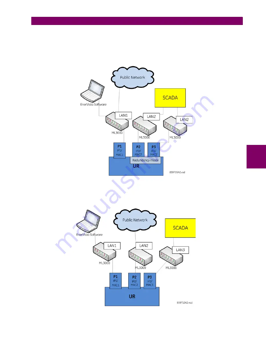
The topology in the following figure provides local configuration/monitoring through EnerVista software and access to the
public network shared on LAN1, to which port 1 (P1) is connected. There is no redundancy provided on LAN1. Communica-
tions to SCADA is provided through LAN2 and LAN3, to which P2 and respectively P3 are connected and configured to
work in redundant mode. In this configuration, P3 uses the IP and MAC address of P2.
Figure 5–4: MULTIPLE LANS, WITH REDUNDANCY
Multiple LANS, No Redundancy
The following topology provides local configuration/monitoring through EnerVista software on LAN1, to which port 1 (P1) is
connected, access to the public network on LAN2, to which port 2 (P2) is connected and communications with SCADA on
LAN3, to which port 3 (P3) is connected. There is no redundancy.
Figure 5–5: MULTIPLE LANS, NO REDUNDANCY
Summary of Contents for UR Series L90
Page 652: ...A 16 L90 Line Current Differential System GE Multilin A 1 PARAMETER LISTS APPENDIX A A ...
Page 772: ...B 120 L90 Line Current Differential System GE Multilin B 4 MEMORY MAPPING APPENDIX B B ...
Page 802: ...C 30 L90 Line Current Differential System GE Multilin C 7 LOGICAL NODES APPENDIX C C ...
Page 812: ...D 10 L90 Line Current Differential System GE Multilin D 1 IEC 60870 5 104 APPENDIX D D ...
Page 824: ...E 12 L90 Line Current Differential System GE Multilin E 2 DNP POINT LISTS APPENDIX E E ...
Page 834: ...F 10 L90 Line Current Differential System GE Multilin F 3 WARRANTY APPENDIX F F ...
Page 846: ...xii L90 Line Current Differential System GE Multilin INDEX ...


