5-54
L90 Line Current Differential System
GE Multilin
5.2 PRODUCT SETUP
5 SETTINGS
5
PTP VLAN ID
•
This setting selects the value of the ID field in the 802.1Q VLAN tag in request messages issued by the relay’s peer
delay mechanism. It is provided in compliance with PP. As these messages have a destination address that indicates
they are not to be bridged, their VLAN ID serves no function, and so may be left at its default value.
•
Depending on the characteristics of the device to which the relay is directly linked, VLAN ID may have no effect.
•
This setting applies to all of the relay’s PTP capable ports.
b) SNTP PROTOCOL
PATH: SETTINGS
PRODUCT SETUP
REAL TIME CLOCK
SNTP PROTOCOL
The L90 supports the Simple Network Time Protocol specified in RFC-2030. With SNTP, the L90 can obtain clock time over
an Ethernet network. The L90 acts as an SNTP client to receive time values from an SNTP/NTP server, usually a dedicated
product using a GPS receiver to provide an accurate time. Unicast SNTP is supported. The UR-series relays do not support
the broadcast, multicast or anycast SNTP functionality.
The
SNTP FUNCTION
setting enables or disabled the SNTP feature on the L90.
To use SNTP,
SNTP SERVER IP ADDR
must be set to the SNTP/NTP server IP address. Once this address is set and
SNTP
FUNCTION
is “Enabled”, the L90 attempts to obtain time values from the SNTP/NTP server. Since many time values are
obtained and averaged, it generally takes three to four minutes until the L90 clock is closely synchronized with the SNTP/
NTP server. It takes up to two minutes for the L90 to signal an SNTP self-test error if the server is offline.
The
SNTP UDP PORT NUMBER
is 123 for normal SNTP operation. If SNTP is not required, close the port by setting it to 0.
When the
SNTP UDP PORT NUMBER
is set to 0, the change takes effect when the L90 is restarted.
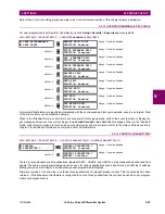
SNTP PROTOCOL
SNTP FUNCTION:
Disabled
Range: Enabled, Disabled
MESSAGE
SNTP SERVER IP ADDR:
0.0.0.0
Range: Standard IP address format
MESSAGE
SNTP UDP PORT
NUMBER: 123
Range: 0 to 65535 in steps of 1
NOTE
Summary of Contents for UR Series L90
Page 652: ...A 16 L90 Line Current Differential System GE Multilin A 1 PARAMETER LISTS APPENDIX A A ...
Page 772: ...B 120 L90 Line Current Differential System GE Multilin B 4 MEMORY MAPPING APPENDIX B B ...
Page 802: ...C 30 L90 Line Current Differential System GE Multilin C 7 LOGICAL NODES APPENDIX C C ...
Page 812: ...D 10 L90 Line Current Differential System GE Multilin D 1 IEC 60870 5 104 APPENDIX D D ...
Page 824: ...E 12 L90 Line Current Differential System GE Multilin E 2 DNP POINT LISTS APPENDIX E E ...
Page 834: ...F 10 L90 Line Current Differential System GE Multilin F 3 WARRANTY APPENDIX F F ...
Page 846: ...xii L90 Line Current Differential System GE Multilin INDEX ...


