GE Multilin
L90 Line Current Differential System
2-17
2 PRODUCT DESCRIPTION
2.2 PILOT CHANNEL RELAYING
2
2.2.3 LOOPBACK TEST
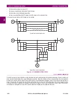
This option allows the user to test the relay at one terminal of the line by
looping
the transmitter output to the receiver input;
at the same time, the signal sent to the remote will not change. A local loopback feature is included in the relay to simplify
single ended testing.
2.2.4 DIRECT TRANSFER TRIPPING
The L90 includes provision for sending and receiving a single-pole direct transfer trip (DTT) signal from current differential
protection between the L90 relays at the line terminals using the pilot communications channel. The user may also initiate
an additional eight pilot signals with an L90 communications channel to create trip, block, or signaling logic. A FlexLogic
operand, an external contact closure, or a signal over the LAN communication channels can be assigned for that logic.
Summary of Contents for UR Series L90
Page 652: ...A 16 L90 Line Current Differential System GE Multilin A 1 PARAMETER LISTS APPENDIX A A ...
Page 772: ...B 120 L90 Line Current Differential System GE Multilin B 4 MEMORY MAPPING APPENDIX B B ...
Page 802: ...C 30 L90 Line Current Differential System GE Multilin C 7 LOGICAL NODES APPENDIX C C ...
Page 812: ...D 10 L90 Line Current Differential System GE Multilin D 1 IEC 60870 5 104 APPENDIX D D ...
Page 824: ...E 12 L90 Line Current Differential System GE Multilin E 2 DNP POINT LISTS APPENDIX E E ...
Page 834: ...F 10 L90 Line Current Differential System GE Multilin F 3 WARRANTY APPENDIX F F ...
Page 846: ...xii L90 Line Current Differential System GE Multilin INDEX ...


