5-50
L90 Line Current Differential System
GE Multilin
5.2 PRODUCT SETUP
5 SETTINGS
5
PATH: SETTINGS
PRODUCT SETUP
COMMUNICATIONS
IEC 60870-5-104 PROTOCOL
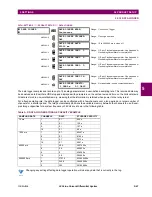
IEC NETWORK CLIENT
ADDRESSES
The UR can specify a maximum of five clients for its IEC 104 connections. These are IP addresses for the controllers to
which the UR can connect.
A maximum of two simultaneous connections are supported at any given time.
5.2.6 MODBUS USER MAP
PATH: SETTINGS
PRODUCT SETUP
MODBUS USER MAP
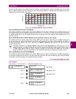
The Modbus user map provides read-only access for up to 256 registers. To obtain a memory map value, enter the desired
address in the
ADDRESS
line (converted from hex to decimal format). The corresponding value displays in the
VALUE
line. A
value of “0” in subsequent register
ADDRESS
lines automatically returns values for the previous
ADDRESS
lines incremented
by “1”. An address value of “0” in the initial register means “none” and values of “0” display for all registers. Different
ADDRESS
values can be entered as required in any of the register positions.
5.2.7 REAL TIME CLOCK
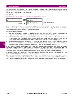
a) MAIN MENU
PATH: SETTINGS
PRODUCT SETUP
REAL TIME CLOCK
IEC NETWORK
CLIENT ADDRESSES
CLIENT ADDRESS 1:
0.0.0.0
Range: Standard IPV4 address format
MESSAGE
CLIENT ADDRESS 2:
0.0.0.0
Range: Standard IPV4 address format
MESSAGE
CLIENT ADDRESS 3:
0.0.0.0
Range: Standard IPV4 address format
MESSAGE
CLIENT ADDRESS 4:
0.0.0.0
Range: Standard IPV4 address format
MESSAGE
CLIENT ADDRESS 5:
0.0.0.0
Range: Standard IPV4 address format
MODBUS USER MAP
ADDRESS
1:
0
VALUE:
0
Range: 0 to 65535 in steps of 1
MESSAGE
ADDRESS
2:
0
VALUE:
0
Range: 0 to 65535 in steps of 1
MESSAGE
ADDRESS
3:
0
VALUE:
0
Range: 0 to 65535 in steps of 1
MESSAGE
ADDRESS 256:
0
VALUE:
0
Range: 0 to 65535 in steps of 1
REAL TIME
CLOCK
SYNCRONIZING SOURCE:
None
Range: None, PP/IRIG-B/PTP/SNTP, IRIG-B/PP/PTP/
SNTP, PP/PTP/IRIG-B/SNTP
MESSAGE
PRECISION TIME
PROTOCOL (1588)
See below
MESSAGE
SNTP PROTOCOL
See below
MESSAGE
LOCAL TIME
See below
Summary of Contents for UR Series L90
Page 652: ...A 16 L90 Line Current Differential System GE Multilin A 1 PARAMETER LISTS APPENDIX A A ...
Page 772: ...B 120 L90 Line Current Differential System GE Multilin B 4 MEMORY MAPPING APPENDIX B B ...
Page 802: ...C 30 L90 Line Current Differential System GE Multilin C 7 LOGICAL NODES APPENDIX C C ...
Page 812: ...D 10 L90 Line Current Differential System GE Multilin D 1 IEC 60870 5 104 APPENDIX D D ...
Page 824: ...E 12 L90 Line Current Differential System GE Multilin E 2 DNP POINT LISTS APPENDIX E E ...
Page 834: ...F 10 L90 Line Current Differential System GE Multilin F 3 WARRANTY APPENDIX F F ...
Page 846: ...xii L90 Line Current Differential System GE Multilin INDEX ...


