GE Multilin
L90 Line Current Differential System
2-1
2 PRODUCT DESCRIPTION
2.1 INTRODUCTION
2
2 PRODUCT DESCRIPTION 2.1INTRODUCTION
2.1.1 OVERVIEW
The L90 Line Current Differential System is a digital current differential relay system with an integral communications chan-
nel interface. It is a complete line terminal protection and control system, able to deliver protection as either a line differen-
tial and/or distance device. Both distance and line differential elements can run simultaneously.
The L90 is intended to provide complete protection for transmission lines of any voltage level. Both three phase and single
phase tripping schemes are available. Models of the L90 are available for application on both two and three terminal lines.
The L90 uses per phase differential at 64 kbps transmitting two phaselets per cycle. The current differential scheme is
based on innovative patented techniques developed by GE. The L90 algorithms are based on the Fourier transform–
phaselet approach and an adaptive statistical restraint. The restraint is similar to a traditional percentage differential
scheme, but is adaptive based on relay measurements. When used with a 64 kbps channel, the innovative phaselets
approach yields an operating time of 1.0 to 1.5 cycles (typical). The adaptive statistical restraint approach provides both
more sensitive and more accurate fault sensing. This allows the L90 to detect relatively higher impedance single line to
ground faults that existing systems may not. The basic current differential element operates on current input only. Long
lines with significant capacitance can benefit from charging current compensation if terminal voltage measurements are
applied to the relay. The voltage input is also used for some protection and monitoring features such as directional ele-
ments, fault locator, metering, and distance backup. In addition, the L90 provides local restricted ground fault protection.
The L90 is designed to operate over different communications links with various degrees of noise encountered in power
systems and communications environments. Since correct operation of the relay is completely dependent on data received
from the remote end, special attention must be paid to information validation. The L90 incorporates a high degree of secu-
rity by using a 32-bit CRC (cyclic redundancy code) inter-relay communications packet.
In addition to current differential protection, the relay provides multiple backup protection for phase and ground faults. For
overcurrent protection, the time overcurrent curves may be selected from a selection of standard curve shapes or a custom
FlexCurve™ for optimum co-ordination. Additionally, five zones of phase and ground distance protection with power swing
blocking, out-of-step tripping, line pickup, load encroachment, and six pilot schemes are included.
The L90 incorporates charging current compensation for applications on very long transmission lines without loss of sensi-
tivity. The line capacitive current is removed from the terminal phasors.
For breaker-and-a-half or ring applications, the L90 design provides secure operation during external faults with possible
CT saturation.
Voltage, current, and power metering is built into the relay as a standard feature. Current parameters are available as total
waveform RMS magnitude, or as fundamental frequency only RMS magnitude and angle (phasor).
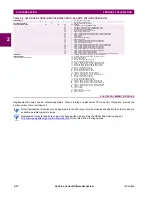
Table 2–1: DEVICE NUMBERS AND FUNCTIONS
DEVICE
NUMBER
FUNCTION
DEVICE
NUMBER
FUNCTION
21G
Ground distance
52
AC circuit breaker
21P
Phase distance
59N
Neutral overvoltage
25
Synchrocheck
59P
Phase overvoltage
27P
Phase undervoltage
59X
Auxiliary overvoltage
27X
Auxiliary undervoltage
67N
Neutral directional overcurrent
32N
Wattmetric zero-sequence directional
67P
Phase directional overcurrent
50BF
Breaker failure
67_2
Negative-sequence directional overcurrent
50DD
Adaptive fault detector
(sensitive current disturbance detector)
68
Power swing blocking
78
Out-of-step tripping
50G
Ground instantaneous overcurrent
79
Automatic recloser
50N
Neutral instantaneous overcurrent
81O
Overfrequency
50P
Phase instantaneous overcurrent
81ROCOF
Rate of change of frequency
50_2
Negative-sequence instantaneous overcurrent
81U
Underfrequency
51G
Ground time overcurrent
87G
Restricted ground fault
51N
Neutral time overcurrent
87L
Segregated line current differential
51P
Phase time overcurrent
87LG
Ground differential
51_2
Negative-sequence time overcurrent
Summary of Contents for UR Series L90
Page 652: ...A 16 L90 Line Current Differential System GE Multilin A 1 PARAMETER LISTS APPENDIX A A ...
Page 772: ...B 120 L90 Line Current Differential System GE Multilin B 4 MEMORY MAPPING APPENDIX B B ...
Page 802: ...C 30 L90 Line Current Differential System GE Multilin C 7 LOGICAL NODES APPENDIX C C ...
Page 812: ...D 10 L90 Line Current Differential System GE Multilin D 1 IEC 60870 5 104 APPENDIX D D ...
Page 824: ...E 12 L90 Line Current Differential System GE Multilin E 2 DNP POINT LISTS APPENDIX E E ...
Page 834: ...F 10 L90 Line Current Differential System GE Multilin F 3 WARRANTY APPENDIX F F ...
Page 846: ...xii L90 Line Current Differential System GE Multilin INDEX ...


