5-344
L90 Line Current Differential System
GE Multilin
5.8 INPUTS/OUTPUTS
5 SETTINGS
5
b) DIRECT INPUTS
PATH: SETTINGS
INPUTS/OUTPUTS
DIRECT
DIRECT INPUTS
The
DIRECT INPUT 1-1(8) DEFAULT
setting selects the logic state of this particular bit used for this point if the local relay has
just completed startup or the local communications channel is declared to have failed. Setting
DIRECT INPUT 1-1(8) DEFAULT
to “On” means that the corresponding local FlexLogic operand (
DIRECT I/P 1-1(8)
) will have logic state “1” on relay startup or
during communications channel failure. When the channel is restored, the operand logic state reflects the actual state of
the corresponding remote direct output.
c) DIRECT OUTPUTS
PATH: SETTINGS
INPUTS/OUTPUTS
DIRECT
DIRECT OUTPUTS
The relay provides eight direct outputs that are conveyed on communications channel 1 (numbered 1-1 through 1-8) and
eight direct outputs that are conveyed on communications channel 2 (numbered 2-1 through 2-8). Each digital point in the
message must be programmed to carry the state of a specific FlexLogic operand. The setting above is used to select the
operand which represents a specific function (as selected by the user) to be transmitted.
Direct outputs 2-1 to 2-8 are only functional on three-terminal systems.
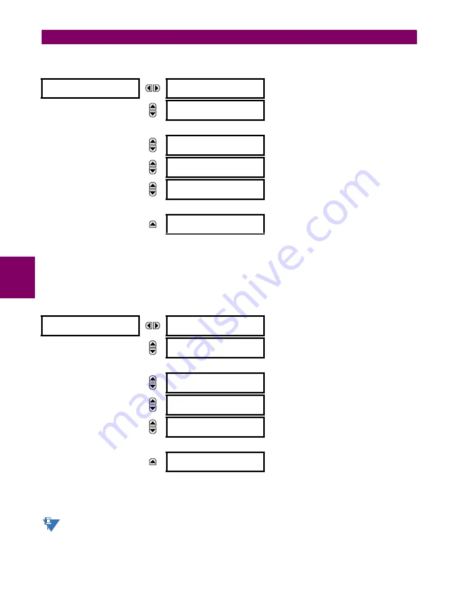
DIRECT INPUTS
DIRECT INPUT 1-1
DEFAULT: Off
Range: Off, On
MESSAGE
DIRECT INPUT 1-2
DEFAULT: Off
Range: Off, On
MESSAGE
DIRECT INPUT 1-8
DEFAULT: Off
Range: Off, On
MESSAGE
DIRECT INPUT 2-1
DEFAULT: Off
Range: Off, On
MESSAGE
DIRECT INPUT 2-2
DEFAULT: Off
Range: Off, On
MESSAGE
DIRECT INPUT 2-8
DEFAULT: Off
Range: Off, On
DIRECT OUTPUTS
DIRECT OUTPUT 1-1:
Off
Range: FlexLogic operand
MESSAGE
DIRECT OUTPUT 1-2:
Off
Range: FlexLogic operand
MESSAGE
DIRECT OUTPUT 1-8:
Off
Range: FlexLogic operand
MESSAGE
DIRECT OUTPUT 2-1:
Off
Range: FlexLogic operand
MESSAGE
DIRECT OUTPUT 2-2:
Off
Range: FlexLogic operand
MESSAGE
DIRECT OUTPUT 2-8:
Off
Range: FlexLogic operand
NOTE
Summary of Contents for UR Series L90
Page 652: ...A 16 L90 Line Current Differential System GE Multilin A 1 PARAMETER LISTS APPENDIX A A ...
Page 772: ...B 120 L90 Line Current Differential System GE Multilin B 4 MEMORY MAPPING APPENDIX B B ...
Page 802: ...C 30 L90 Line Current Differential System GE Multilin C 7 LOGICAL NODES APPENDIX C C ...
Page 812: ...D 10 L90 Line Current Differential System GE Multilin D 1 IEC 60870 5 104 APPENDIX D D ...
Page 824: ...E 12 L90 Line Current Differential System GE Multilin E 2 DNP POINT LISTS APPENDIX E E ...
Page 834: ...F 10 L90 Line Current Differential System GE Multilin F 3 WARRANTY APPENDIX F F ...
Page 846: ...xii L90 Line Current Differential System GE Multilin INDEX ...


