2-24
L90 Line Current Differential System
GE Multilin
2.4 SPECIFICATIONS
2 PRODUCT DESCRIPTION
2
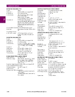
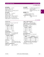
RATE OF CHANGE OF FREQUENCY
df/dt trend:
increasing, decreasing, bi-directional
df/dt pickup level:
0.10 to 15.00 Hz/s in steps of 0.01
df/dt dropout level:
96% of pickup
df/dt level accuracy:
80 mHz/s or 3.5%, whichever is greater
Overvoltage supv.:
0.100 to 3.000 pu in steps of 0.001
Overcurrent supv.:
0.000 to 30.000 pu in steps of 0.001
Pickup delay:
0 to 65.535 s in steps of 0.001
Reset delay:
0 to 65.535 s in steps of 0.001
Timer accuracy:
±3% of operate time or ±1/4 cycle
(whichever is greater)
95% settling time for df/dt: <24 cycles
Operate time:
typically 6.5 cycles at 2
pickup
typically 5.5 cycles at 3
pickup
typically 4.5 cycles at 5
pickup
BREAKER FAILURE
Mode:
1-pole, 3-pole
Current supervision:
phase, neutral current
Current supv. pickup:
0.001 to 30.000 pu in steps of 0.001
Current supv. dropout:
97 to 98% of pickup
Current supv. accuracy:
0.1 to 2.0
CT rating: ±0.75% of reading or ±2% of rated
(whichever is greater)
above 2
CT rating:
±2.5% of reading
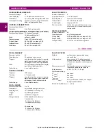
BREAKER ARCING CURRENT
Principle:
accumulates breaker duty (I
2
t) and mea-
sures fault duration
Initiation:
programmable per phase from any Flex-
Logic operand
Compensation for auxiliary relays: 0 to 65.535 s in steps of 0.001
Alarm threshold:
0 to 50000 kA2-cycle in steps of 1
Fault duration accuracy: 0.25 of a power cycle
Availability:
1 per CT bank with a minimum of 2
BREAKER FLASHOVER
Operating quantity:
phase current, voltage and voltage differ-
ence
Pickup level voltage:
0 to 1.500 pu in steps of 0.001
Dropout level voltage:
97 to 98% of pickup
Pickup level current:
0 to 1.500 pu in steps of 0.001
Dropout level current:
97 to 98% of pickup
Level accuracy:
±0.5% or ±0.1% of rated, whichever is
greater
Pickup delay:
0 to 65.535 s in steps of 0.001
Timer accuracy:
±3% of operate time or ±42 ms, which-
ever is greater
Operate time:
<42 ms at 1.10
pickup at 60 Hz
BREAKER RESTRIKE
Principle:
detection of high-frequency overcurrent
condition ¼ cycle after breaker opens
Availability:
one per CT/VT module (not including 8Z
modules)
Pickup level:
0.1 to 2.00 pu in steps of 0.01
Reset delay:
0.000 to 65.535 s in steps of 0.001
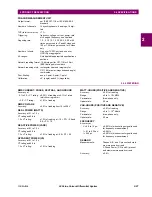
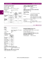
SYNCHROCHECK
Max voltage difference: 0 to 400000 V in steps of 1
Max angle difference:
0 to 100
°
in steps of 1
Max freq. difference:
0.00 to 2.00 Hz in steps of 0.01
Hysteresis for max. freq. diff.: 0.00 to 0.10 Hz in steps of 0.01
Dead source function:
None, LV1 & DV2, DV1 & LV2, DV1 or
DV2, DV1 xor DV2, DV1 & DV2
(L = Live, D = Dead)
AUTORECLOSURE
Two breakers applications
Single- and three-pole tripping schemes
Up to 4 reclose attempts before lockout
Selectable reclosing mode and breaker sequence
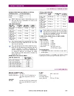
PILOT-AIDED SCHEMES
Direct Underreaching Transfer Trip (DUTT)
Permissive Underreaching Transfer Trip (PUTT)
Permissive Overreaching Transfer Trip (POTT)
Hybrid POTT Scheme
Directional Comparison Blocking Scheme
Directional Comparison Unblocking Scheme (DCUB)
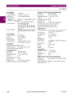
TRIP OUTPUT
Collects trip and reclose input requests and issues outputs to con-
trol tripping and reclosing.
Communications timer delay: 0 to 65535 s in steps of 0.001
Evolving fault timer:
0.000 to 65.535 s in steps of 0.001
Timer accuracy:
±3% of operate time or ±1/4 cycle
(whichever is greater)
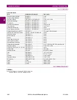
POWER SWING DETECT
Functions:
Power swing block, Out-of-step trip
Characteristic:
Mho or Quad
Measured impedance:
Positive-sequence
Blocking / tripping modes: 2-step or 3-step
Tripping mode:
Early or Delayed
Current supervision:
Pickup level:
0.050 to 30.000 pu in steps of 0.001
Dropout level:
97 to 98% of pickup
Fwd / reverse reach (sec.
): 0.10 to 500.00
in steps of 0.01
Left and right blinders (sec.
): 0.10 to 500.00
in steps of 0.01
Impedance accuracy:
±5%
Fwd / reverse angle impedances: 40 to 90° in steps of 1
Angle accuracy:
±2°
Characteristic limit angles: 40 to 140° in steps of 1
Timers:
0.000 to 65.535 s in steps of 0.001
Timer accuracy:
±3% of operate time or ±1/4 cycle
(whichever is greater)
Summary of Contents for UR Series L90
Page 652: ...A 16 L90 Line Current Differential System GE Multilin A 1 PARAMETER LISTS APPENDIX A A ...
Page 772: ...B 120 L90 Line Current Differential System GE Multilin B 4 MEMORY MAPPING APPENDIX B B ...
Page 802: ...C 30 L90 Line Current Differential System GE Multilin C 7 LOGICAL NODES APPENDIX C C ...
Page 812: ...D 10 L90 Line Current Differential System GE Multilin D 1 IEC 60870 5 104 APPENDIX D D ...
Page 824: ...E 12 L90 Line Current Differential System GE Multilin E 2 DNP POINT LISTS APPENDIX E E ...
Page 834: ...F 10 L90 Line Current Differential System GE Multilin F 3 WARRANTY APPENDIX F F ...
Page 846: ...xii L90 Line Current Differential System GE Multilin INDEX ...


