3-46
T60 Transformer Protection System
GE Multilin
3.4 MANAGED ETHERNET SWITCH MODULES
3 HARDWARE
3
b) CONFIGURING LAN COMMUNICATIONS
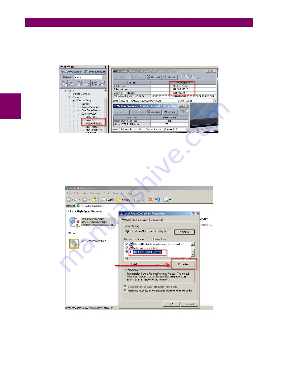
The following procedure describes how to initially configure the Ethernet switch to work on your LAN.
1.
Initiate communications from a PC to the T60 through a front panel serial connection (refer to the
Configuring serial
communications
section in chapter 1 for details), or if you are familiar with the UR keypad you can use it to set up the
network IP address and check the Modbus slave address and Modbus TCP port.
2.
Ensure that the PC and the T60 are on the same IP network.
If your computer is on another network or has a dynamic IP address assigned upon a network login, then setup your
own IP address as follows
2.1.
From the Windows Start Menu, select the
Settings > Network Connections
menu item.
2.2.
Right-click on the
Local Area Connection
icon and select the
Properties
item. This will open the LAN proper-
ties window.
2.3.
Click the
Properties
button as shown below.
&OLFNWKH3URSHUWLHVEXWWRQ
$&'5
Summary of Contents for UR T60
Page 10: ...x T60 Transformer Protection System GE Multilin TABLE OF CONTENTS ...
Page 14: ...xiv T60 Transformer Protection System GE Multilin 0 1 BATTERY DISPOSAL 0 BATTERY DISPOSAL 0 ...
Page 34: ...1 20 T60 Transformer Protection System GE Multilin 1 5 USING THE RELAY 1 GETTING STARTED 1 ...
Page 436: ...5 298 T60 Transformer Protection System GE Multilin 5 10 TESTING 5 SETTINGS 5 ...
Page 678: ...C 30 T60 Transformer Protection System GE Multilin C 7 LOGICAL NODES APPENDIX C C ...
Page 688: ...D 10 T60 Transformer Protection System GE Multilin D 1 IEC 60870 5 104 PROTOCOL APPENDIX D D ...
Page 700: ...E 12 T60 Transformer Protection System GE Multilin E 2 DNP POINT LISTS APPENDIX E E ...


