GE Multilin
T60 Transformer Protection System
1-15
1 GETTING STARTED
1.3 ENERVISTA UR SETUP SOFTWARE
1
1.3.5 CONNECTING TO THE T60 RELAY
When unable to connect because of an "ACCESS VIOLATION," access
Device Setup
and refresh the order code for the
device.
1.
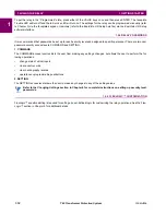
Open the Display Properties window through the Site List tree as shown below:
2.
The Display Properties window will open with a status indicator on the lower left of the EnerVista UR Setup window.
3.
If the status indicator is red, verify that the Ethernet network cable is properly connected to the Ethernet port on the
back of the relay and that the relay has been properly setup for communications (steps A and B earlier).
If a relay icon appears in place of the status indicator, than a report (such as an oscillography or event record) is open.
Close the report to re-display the green status indicator.
4.
The Display Properties settings can now be edited, printed, or changed according to user specifications.
Refer to chapter 4 in this manual and the EnerVista UR Setup Help File for more information about the
using the EnerVista UR Setup software interface.
QUICK ACTION HOT LINKS
The EnerVista UR Setup software has several new quick action buttons that provide users with instant access to several
functions that are often performed when using T60 relays. From the online window, users can select which relay to interro-
gate from a pull-down window, then click on the button for the action they wish to perform. The following quick action func-
tions are available:
•
View the T60 event record.
•
View the last recorded oscillography record.
•
View the status of all T60 inputs and outputs.
•
View all of the T60 metering values.
•
View the T60 protection summary.
842743A3.CDR
Communications status indicators:
Green = OK
Red = No communications
UR icon = report is open
Quick action hot links
Expand the site list by double-clicking
or selecting the +/– box.
NOTE
Summary of Contents for UR T60
Page 10: ...x T60 Transformer Protection System GE Multilin TABLE OF CONTENTS ...
Page 14: ...xiv T60 Transformer Protection System GE Multilin 0 1 BATTERY DISPOSAL 0 BATTERY DISPOSAL 0 ...
Page 34: ...1 20 T60 Transformer Protection System GE Multilin 1 5 USING THE RELAY 1 GETTING STARTED 1 ...
Page 436: ...5 298 T60 Transformer Protection System GE Multilin 5 10 TESTING 5 SETTINGS 5 ...
Page 678: ...C 30 T60 Transformer Protection System GE Multilin C 7 LOGICAL NODES APPENDIX C C ...
Page 688: ...D 10 T60 Transformer Protection System GE Multilin D 1 IEC 60870 5 104 PROTOCOL APPENDIX D D ...
Page 700: ...E 12 T60 Transformer Protection System GE Multilin E 2 DNP POINT LISTS APPENDIX E E ...


