GE Multilin
T60 Transformer Protection System
7-3
7 COMMANDS AND TARGETS
7.1 COMMANDS
7
7.1.5 RELAY MAINTENANCE
PATH: COMMANDS
RELAY MAINTENANCE
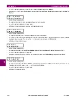
This menu contains commands for relay maintenance purposes. Commands for the lamp test and order code are activated
by changing a command setting to “Yes” and pressing the ENTER key. The command setting will then automatically revert
to “No”. The service command is activated by entering a numerical code and pressing the ENTER key.
The
PERFORM LAMPTEST
command turns on all faceplate LEDs and display pixels for a short duration. The
UPDATE
ORDER CODE
command causes the relay to scan the backplane for the hardware modules and update the order code to
match. If an update occurs, the following message is shown.
There is no impact if there have been no changes to the hardware modules. When an update does not occur, the
ORDER
CODE NOT UPDATED
message will be shown.
The
SERVICE COMMAND
is used to perform specific T60 service actions. Presently, there is only one service action available.
Code “101” is used to clear factory diagnostic information stored in the non-volatile memory. If a code other than “101” is
entered, the command will be ignored and no actions will be taken. Various self-checking diagnostics are performed in the
background while the T60 is running, and diagnostic information is stored on the non-volatile memory from time to time
based on the self-checking result. Although the diagnostic information is cleared before the T60 is shipped from the factory,
the user may want to clear the diagnostic information for themselves under certain circumstances. For example, it may be
desirable to clear diagnostic information after replacement of hardware. Once the diagnostic information is cleared, all self-
checking variables are reset to their initial state and diagnostics will restart from scratch.
7.1.6 PHASOR MEASUREMENT UNIT ONE-SHOT
PATH: COMMANDS
PMU ONE-SHOT
This feature allows pre-scheduling a PMU measurement at a specific point in time. This functionality can be used to test for
accuracy of the PMU, and for manual collection of synchronized measurements through the system, as explained below.
When enabled, the function continuously compares the present time with the pre-set
PMU ONE-SHOT TIME
. When the two
times match, the function compares the present sequence number of the measured synchrophasors with the pre-set
PMU
ONE-SHOT SEQUENCE NUMBER
. When the two numbers match, the function freezes the synchrophasor actual values and
the corresponding protocol data items for 30 seconds. This allows manual read-out of the synchrophasor values for the pre-
set time and pre-set sequence number (via the faceplate display, supported communication protocols such as Modbus or
DNP, and the EnerVista UR Setup software).
When freezing the actual values the function also asserts a
PMU ONE-SHOT OP
FlexLogic™ operand. This operand may be
configured to drive an output contact and trigger an external measuring device such as a digital scope with the intent to ver-
ify the accuracy of the PMU under test.
With reference to the figure below, the PMU one-shot function (when enabled) controls three FlexLogic™ operands:
COMMANDS
RELAY MAINTENANCE
PERFORM LAMPTEST?
No
Range: No, Yes
UPDATE ORDER CODE?
No
Range: No, Yes
SERVICE COMMAND:
0
Range: 0, 101
UPDATING...
PLEASE WAIT
COMMANDS
PMU ONE-SHOT
PMU ONE-SHOT
FUNCTION: Disabled
Range: Enabled, Disabled
PMU ONE-SHOT
SEQUENCE NUMBER: 0
Range: 0 to nominal frequency – 1 in steps of 1
PMU ONE-SHOT TIME:
2005/06/14 7:58:35
Range: 24h time format
Summary of Contents for UR T60
Page 10: ...x T60 Transformer Protection System GE Multilin TABLE OF CONTENTS ...
Page 14: ...xiv T60 Transformer Protection System GE Multilin 0 1 BATTERY DISPOSAL 0 BATTERY DISPOSAL 0 ...
Page 34: ...1 20 T60 Transformer Protection System GE Multilin 1 5 USING THE RELAY 1 GETTING STARTED 1 ...
Page 436: ...5 298 T60 Transformer Protection System GE Multilin 5 10 TESTING 5 SETTINGS 5 ...
Page 678: ...C 30 T60 Transformer Protection System GE Multilin C 7 LOGICAL NODES APPENDIX C C ...
Page 688: ...D 10 T60 Transformer Protection System GE Multilin D 1 IEC 60870 5 104 PROTOCOL APPENDIX D D ...
Page 700: ...E 12 T60 Transformer Protection System GE Multilin E 2 DNP POINT LISTS APPENDIX E E ...


