background image


1-10 

VersaMax  PROFINET Scanner Manual 

– December 2013 

 GFK-2721A  


1


The PROFINET Scanner supports the following network media type and distances. 

Media Type 

Connector 

Type 

Wavelength 

(nm) 

Media 

Type 

Core 

Size(μm) 

Modal Bandwidth 

(MHz 

– Km) 

Distance (m) 

100BASE-FX 

SC or  
SC-Duplex 

1300 

MMF 

62.5 

500 

– 2,000 (Full-

Duplex) 

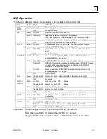
– 400 (Half-

Duplex) 

50 

400 

50 

500 

10/100BASE-T  

RJ45 

CAT5/ 
CAT5e/ 
CAT6 

100 
(maximum) 

VersaMax PNS modules and other participating modules can be connected in a 
daisy-chain/line, star, or ring (redundant media) topology.  

VLAN Priority Settings for the PROFINET Scanner 

The VersaMax PNS supports VLAN Priorities as well as incoming traffic that does not include a 
VLAN header. The Ethernet switch in the PROFINET Scanner supports two traffic classes, 
assigning VLAN Priorities to these classes based on whether rapid arrival of the traffic is critical 
to the system, or less important.   

VLAN Priority 

Preference / Traffic Class 

7, 6, 5 

Realtime (High Priority). This includes the following Ethernet traffic: 
PTCP, MRP, MRRT, RT_CLASS_2, RT_CLASS_1, RT_CLASS_UDP, High Priority 
RTA_CLASS_1, High Priority RTA_CLASS_UDP, Low Priority RTA_CLASS_1, Low 
Priority RTA_CLASS_UDP 

4, 3, 2, 1, 0 

Non-realtime (Lower Priority), This includes the following Ethernet traffic: IP, DCP, 
other untagged traffic 

An external switch that supports only two traffic queues must be configured like the PROFINET 
Scanner, as listed in the table above. An external switch that does not support a VLAN priority 
mapping that exactly matches the mapping used by the VersaMax PROFINET Scanner can be 
used if it can be configured with the following relationships between VLAN priorities: 

  VLAN Priority 7 is forwarded with at least as much preference as VLAN Priority 6. 

  VLAN Priority 6 is forwarded with at least as much preference as VLAN Priority 5. 

  VLAN Priority 5 is forwarded with more preference than VLAN Priorities 0, 1, 2, 3 and 4. 

If the external switch does not allow VLAN priority 4 to be treated differently from priority 5, it 
should be used only if no device on the network will generate VLAN Priority 4 Ethernet Traffic.


Summary of Contents for VersaMax GFK-2721A

Page 1: ...GE Intelligent Platforms Programmable Control Products VersaMax PROFINET Scanner Manual GFK 2721A December 2013...

Page 2: ...he information contained herein does not purport to cover all details or variations in hardware or software nor to provide for every possible contingency in connection with installation operation or m...

Page 3: ...0 2010 if toll free 800 option is unavailable Technical Support Email support ip ge com Customer Care Email customercare ip ge com Primary language of support English Europe the Middle East and Africa...

Page 4: ......

Page 5: ...l 2 5 Installing Power Supplies 2 7 PROFINET Scanner Power up and Restart 2 8 LED Operation 2 9 Special LED Blink Patterns 2 10 Firmware Updates 2 11 Firmware Update for Modules in the Remote Node 2 1...

Page 6: ...Alarms 4 5 Clearing Faults on VersaMax Analog Modules 4 7 PROFINET Module Loss Add Mismatch Faults 4 8 Diagnostics for BEM003 PROFIBUS DP Networks 4 9 PROFINET Specifications A 1 PROFINET Protocol Sup...

Page 7: ...nd updating firmware It also describes powerup and restart and LED operation Chapter 3 Configuration describes how to configure the PROFINET Scanner and its associated I O devices Chapter 4 Diagnostic...

Page 8: ...the individual module configurations The VersaMax PROFINET Scanner automatically converts between data formats used by VersaMax modules and the big endian format used for PROFINET communications Input...

Page 9: ...er optic media connectors PNS001 PWR1 L PWR2 R OK FAULT CONNECT LAN PORT 1 L PORT 2 R MAINT COMM The PROFINET Scanner supports the use of either one or two power supplies Use of the second power suppl...

Page 10: ...B connector USB 2 0 compliant running at Full speed 12 MHz PNS Status and Control Bits 32 input status bits and 32 output control bits I O Data Update on the PROFINET network Configurable 1ms 2ms 4ms...

Page 11: ...closed VersaMax PROFINET Scanner LEDs Power Supply LEDs Each Power Supply LED PWR1 and PWR2 is ON solid green when a minimum level of power is being supplied on the corresponding power supply connect...

Page 12: ...ED goes OFF If the PROFINET Scanner has an assigned network name the CONNECT LED is OFF after a successful power up It turns ON solid Green when the primary IO Controller has established communication...

Page 13: ...ace the VersaMax stick in Maintenance mode This switch is located behind the door on the front panel of the PNS to prevent accidental operation To change from Normal Mode to Maintenance Mode press and...

Page 14: ...and DC supplies is supported but both should be isolated or both non isolated Either one of the power supplies must be capable of supplying all the power required by the node The two supplies do not...

Page 15: ...T Scanner requires at least one network be operating at full duplex for a connection to remain established The PROFINET protocol may be sent and received over either or both of the two external ports...

Page 16: ...igh Priority This includes the following Ethernet traffic PTCP MRP MRRT RT_CLASS_2 RT_CLASS_1 RT_CLASS_UDP High Priority RTA_CLASS_1 High Priority RTA_CLASS_UDP Low Priority RTA_CLASS_1 Low Priority R...

Page 17: ...be configured as the Media Redundancy Manager MRM and all the other devices must be configured as Media Redundancy Clients MRCs The PNS can be configured to be an MRC Configuring the PNS as an MRC al...

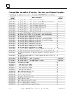
Page 18: ...og Output Module 13 Bit Voltage 8 Channels All IC200ALG326 Analog Output Module 13 Bit Current 8 Channels All IC200ALG327 Analog Output Module 13 Bit Voltage 12 Channels All IC200ALG328 Analog Output...

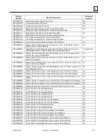
Page 19: ...C200MDD845 Mixed 16 Point Grouped Input 24VDC Pos Neg Logic 8 Pt Relay Output 2 0A per Pt Isolated Form A All IC200MDD846 Mixed 120VAC Input 8 Point Output Relay 2 0A per Point 8 Point Module All IC20...

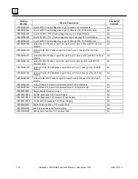
Page 20: ...nt 1 Group of 16 w ESCP 16 Point Module All IC200MDL742 Output 24VDC Positive Logic 0 5A per Point 2 Groups of 16 w ESCP 32 Point Module All IC200MDL743 Output 5 12 24VDC Negative Logic 0 5A per Point...

Page 21: ...Installing the Module on a DIN Rail o Removing the Module from the DIN Rail o Panel Mounting o Grounding o Installing Power Supplies PROFINET Scanner Powerup and Restart LED Operation o Special LED Bl...

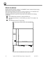
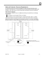
Page 22: ...nd below the equipment and 2 54cm 1in to the left of the PNS module In addition to clearances required for cooling space must be allowed for the following requirements Allow sufficient finger clearanc...

Page 23: ...e manufacturer Cable Clearance Example In this example a PNS002 module is installed with a fiber optic cable that has the following characteristics SC Duplex connector length 27mm 1 07 inches Manufact...

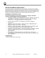
Page 24: ...cts bearing the UL marking for Hazardous Locations or ATEX marking for explosive atmospheres EQUIPMENT LABELED WITH REFERENCE TO CLASS I GROUPS A B C D DIV 2 HAZARDOUS LOCATIONS IS SUITABLE FOR USE IN...

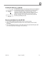
Page 25: ...a panel using screws spaced approximately 6 inches 5 24cm apart Modules snap easily onto the DIN rail No tools are required for mounting or grounding to the rail Removing the Module from the DIN Rail...

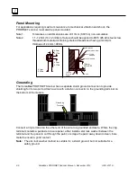
Page 26: ...FLAT WASHER CPU TAPPED HOLE IN PANEL 5 1mm 0 200in 4 3mm 0 170in 4 3mm 0 170in Grounding The VersaMax PROFINET Scanner has a separate shield ground connection to provide shielding for its two ports At...

Page 27: ...upply is used an IC200ACC200 Empty Filler module may be installed in the empty power supply slot Installing a Redundant Power Supply A redundant power supply can be installed on the PROFINET Scanner w...

Page 28: ...e power supply or if there are two power supplies with the same power source requiring both to be powered down Otherwise the PROFINET Scanner may lose power and turn off PROFINET Scanner Power up and...

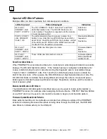
Page 29: ...FINET Scanner has not been assigned a name Fast Blink PROFINET connection is being blocked because PROFINET Scanner is updating the firmware of a module in the node or PROFINET Scanner is in Maintenan...

Page 30: ...T Scanner detects a fatal error it attempts to write diagnostic data to nonvolatile storage The OK LED fast blinks amber If the module has been configured to blink fatal error codes it starts blinking...

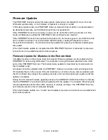
Page 31: ...connections are re established and control resumes Firmware Update for Modules in the Remote Node VersaMax modules in the remote node that support firmware updates can be updated via the PROFINET Sca...

Page 32: ...next available number from 1 to 256 After the computer assigns the USB port a COM port number that computer uses the same COM port number each time it connects to that Scanner module During firmware u...

Page 33: ...pter discusses the following topics Configuration Overview o Basic Configuration Steps o Configuration Tool Adding a VersaMax PROFINET Scanner to a LAN o Configuring VersaMax PROFINET Scanner Paramete...

Page 34: ...es of IO Devices use GSDML files to describe their capabilities The PROFINET IO configuration tool imports these GSDML files and incorporates the devices into the configuration Configure the parameter...

Page 35: ...e By default the service is disabled The network parameters of the PNS IP Address subnet mask and gateway IP should either be configured to match the fixed parameters assigned to the PNS using a DCP T...

Page 36: ...tically selects redundant control by setting the Redundancy Mode parameter to HSB CPU Redundancy When the VersaMax PNS is not configured in an HSB CPU Redundancy system the VersaMax PNS Programmer aut...

Page 37: ...Scanner remote node can contain the module types listed in Chapter 1 It cannot contain the following expansion modules or communications modules Unsupported VersaMax Modules Asi Network Master Module...

Page 38: ...hermocouple 7 Channels GFK 1700 IC200BEM003 PROFIBUS DP Master GFK 2740 IC200CMM020 Serial Communications Module Modbus RTU Master GFK 2423 IC200MDD841 Mixed Module 24VDC Positive Logic Input 20 Point...

Page 39: ...40 842 843 844 845 0 25ms IC200MDL643 644 IC200MDD851 Outputs Default Hold Last State When the module has outputs this field specifies how the PROFINET Scanner will handle the module s output data if...

Page 40: ...age 12 Channels IC200ALG328 Analog Output Module 13 Bit Current 12 Channels IC200ALG430 Analog Mixed Module Input Current 4 Channels Output Current 2 Channels IC200ALG431 Analog Mixed Module 0 to 10VD...

Page 41: ...C Range Outputs default to 0V B13 B14 Outputs default to hold last state no jumper IC200ALG322 Analog Output Module 12 Bit Voltage 4 Channels 10 to 10VDC Range Same as IC200ALG321 IC200ALG325 Analog O...

Page 42: ...figurations when the IO Controller establishes an Application Relationship AR with the IO Device If all Application Relationships ARs are lost the IO Device such as a VersaMax PROFINET Scanner does no...

Page 43: ...function of the IO Controller s design and the communication rate configured between the IO Controller and PROFINET scanner For example if a discrete module is configured for a default value of 1 and...

Page 44: ...ing it into a working IO network The IO Device Name and IP Address settings can be updated offline for example in an office setting 1 Remove power from the previous PNS module This should be done befo...

Page 45: ...stics This chapter describes PROFINET Scanner Status and Control Data o Output Control Bits o Input Status Bits Error Handling o Fatal Error Handling o PROFINET Alarms o PROFINET Module Loss Add Misma...

Page 46: ...s completes A transition from 0 to 1 initiates the clear The application program must ensure this bit remains asserted until the Clear Faults ACK status bit indicates that the remote node has executed...

Page 47: ...ply is providing power to the PROFINET Scanner 10 Power2 OK 11 16 Reserved Set to 0 17 Slot1 Clear Faults ACK Used to acknowledge the slot s Clear Faults REQ command bit When the PROFINET Scanner sees...

Page 48: ...recent fatal error is retained This information is available on future power cycles to be retrieved and sent to GE Intelligent Platforms for analysis While diagnostic information is being saved the P...

Page 49: ...s faults after the fault condition has been corrected If no additional conditions exist in memory the FAULT LED is turned OFF and the FAULT status bit is set to 0 The table on the next page lists the...

Page 50: ...nel Over range fault A D value is saturated above 99 5 of hardware range Over Range Correct wiring Provide input in correct range such as 4 20mA Verify output is within range remove shorts 258 Channel...

Page 51: ...odule error condition is still present When these modules are checked periodically a historical log of alarms such as the IO Fault log in Proficy Machine Edition may show new alarms occurring before p...

Page 52: ...e an Application Relationship that includes the slot sub slot is active the VersaMax PROFINET Scanner reports the mismatch using a Plug Wrong Submodule alarm On future connections the module will be r...

Page 53: ...onnect to the BEM003 a Channel Diagnosis Disappears alarm will be reported When using the BEM003 module not all diagnostics in PROFIBUS slaves are reported on PROFINET The status of PROFIBUS slaves ar...

Page 54: ......

Page 55: ...ED will be OFF when the PNS is in Normal mode When the VersaMax PNS enters Maintenance Mode the PNS head end disables control and power to the backplane modules up to the first Power Supply Booster in...

Page 56: ...he PNS is in Maintenance Mode The MAINT LED blinks amber Power to all backplane modules to the left of any Booster Power Supply is disabled All backplane interface signals are tri stated All establish...

Page 57: ...d re enters Normal Mode it will not configure modules in the stick using a previously received Configuration Instead the modules in the stick will be controlled in the same manner as when the PNS has...

Page 58: ......

Page 59: ...ic Protocol RT_CLASS_1 RT_CLASS_2 RTA Real time Acyclic Protocol DCP Discovery and Configuration Protocol CL RPC Connectionless Remote Procedure Call LLDP Link Layer Discovery Protocol transmission on...

Page 60: ...ame Of Station and Station Name Alias filters supported Identification Maintenance I M0 only Context Management by CL RPC Minimum cycle time 1ms Ethernet rate 100 Mbit s full duplex with auto negotiat...

Page 61: ...by HSB Redundancy configuration 3 4 I IC200BEM003 PROFIBUS DP Master configuration 3 6 diagnostics 4 9 IC200PNS001 1 3 IC200PNS002 1 3 Input Status Bits VersaMax PROFINET Scanner 4 3 Installation cabl...

Page 62: ...ax PROFINET Scanner 4 2 T Technical Support See page iii Thermal requirements clearance for 2 2 U USB port 1 11 driver 2 12 V VersaMax analog modules with jumpers 3 8 VersaMax Module Parameters config...

Reviews: