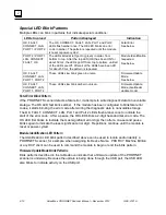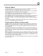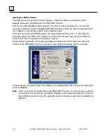
GFK-2721A
Chapter 2 Installation
2-7
2
Installing Power Supplies
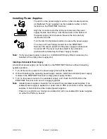
The latch on the power supply must be in the unlocked position,
as illustrated. Power supplies can be installed in either or both
locations on the PROFINET Scanner,
Align the connectors and the latch post and press the power
supply module down firmly, until the two tabs on the bottom of
the power supply click into place. Be sure the tabs are fully
inserted in the slots.
Turn the latch to the locked position to secure the power supply.
To remove a Power Supply module from the PROFINET
Scanner, the source power into the power supply module must
be turned Off. The lever must be rotated to the unlocked
position before detaching the Power Supply module.
Note:
If only one power supply is used, an,
IC200ACC200 Empty Filler module
may be
installed in the empty power supply slot.
Installing a Redundant Power Supply
A redundant power supply can be installed on the PROFINET Scanner without disrupting
system operation:
1. Turn off the source power to the power supply that will be installed.
2. Without disturbing the operating power supply module, install the redundant power supply
module in the PROFINET Scanner’s empty power supply location.
3. Turn on the power source to the redundant supply, and check the PWR LED on the
PROFINET Scanner to be sure it is supplying power.
Note:
Isolated power supplies should not be mixed with non-isolated power supplies. If an
isolated power supply is applied to a power slot on PNS or a booster carrier, all power
supplies in that stick should be isolated power supplies.
There is no restriction on mixing non-isolated AC with non-isolated DC power supplies
on either the PNS or a booster.


