GFK-2721A
Chapter 4 Diagnostics
4-3
4
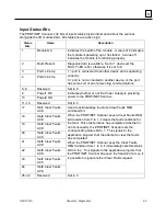
Input Status Bits
The PROFINET Scanner’s 32 bits of input status provide information about the scanner
alongside the I/O module data. All status bits are active high.
Status
Bits
Name
Description
1
Module OK
Indicates the health of the module. A value of 0 indicates
the module is powering up or has failed. A value of 1
indicates the module is functioning properly.
2
Fault Present
Diagnosis data is available. Set to 1 whenever the
FAULT LED is On; otherwise it is set to 0.
3
Port1 Link Up
1 = port is connected to another device and is operating
correctly.
0 = port is not connected to another device, or the port
has some sort of error preventing communications.
4
Port2 Link Up
5
–8
Reserved
Set to 0
9
Power1 OK
Indicates whether or not the Power Supply is providing
power to the PROFINET Scanner.
10
Power2 OK
11
–16
Reserved
Set to 0
17
Slot1 Clear Faults
ACK
Used to acknowledge the slot’s Clear Faults REQ
command bit.
When the PROFINET Scanner sees a Clear Faults REQ
bit transition from 0 to 1, it clears the fault conditions for
that slot. Once that process has completed (whether or
not it succeeds), the PROFINET Scanner sets the
corresponding status bit to 1. This signals to the
application program that the attempt to clear the faults
has completed.
When the PROFINET Scanner sees the Clear Faults
REQ transition from 1 to 0, it immediately sets this status
bit to 0 too. This signals to the application program that
the PROFINET Scanner has seen the transition to 0, so it
is possible to signal another Clear Faults request.
18
Slot2 Clear Faults
ACK
19
Slot3 Clear Faults
ACK
20
Slot4 Clear Faults
ACK
21
Slot5 Clear Faults
ACK
22
Slot6 Clear Faults
ACK
23
Slot7 Clear Faults
ACK
24
Slot8 Clear Faults
ACK
25
–32
Reserved
Set to 0

