Critical Power
Modifications reserved
Page 22/25
GE_UPS_OPM_VHU_0K7_3K0_XUS_V011.docx
Operating Manual
VH700 UL, VH1000 UL, VH1500 UL, VH2000 UL & VH3000 UL
5
COMMUNICATION
CAUTION! RISK OF ELECTRIC SHOCK
The UPS has an internal battery supply with a nominal voltage of 36/72Vdc. The appliance outlets may
be electrically live, even when the UPS is disconnected from the mains.
The UPS contains potentially hazardous voltages. Do not open the unit, there are no user serviceable
parts inside.
WARNING!
Connect only Safety Extra Low Voltage (SELV) Circuits to any of these communication I/O ports.
5.1
USB PORT
The USB port is a plug-in interface port which enables advanced communication between the UPS and the computer (UPS
software required). The interface port is operative as soon as the mains power cord is plugged into a live wall outlet, even if
the UPS is switched off.
For more information please refer to the user manual that comes with the interface software. We strongly recommend to
use only original GE software products in combination with the interface port.
NOTE
The change of some settings can cause the unit to switch from bypass to standby and output power is lost.
5.2
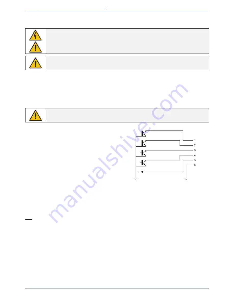
RJ11 PORT
The RJ11 port is a plug-in contact interface port.
Pin #
Function
1
Mains failure
2
General alarm
*)
3
Battery low
4
On bypass
5
Remote UPS shutdown / RxD
6
GND
*) Active if the output voltage of the UPS is no longer
Fig. 5.2
guaranteed due to other circumstances than already indicated by pin 1-3-4. The alarms are listed in section 4.4.10
Absolute Maximum Ratings
DC Characteristics
MIN
MAX
CONDITION MIN
MAX
V
O
Voltage applied on any output pin
-0.2V
48V
V
IH
High-level input voltage
4.0V
I
O
Output sink current
30mA
V
IL
Low-level input voltage
0.4V
V
I
Voltage applied on input pin
-25V
25V
V
OL
Low (active) output voltage Io<1mA
0.4V
Note: Exceeding these ratings may damage the device or anyway affect its reliability
5.3
USB / RS232 / RELAY INTERFACE CARD (OPTION)
The card is equipped with
• USB port as described in 5.1
• RS232 port
• potential free change-over relay contacts for the following alarms:
mains failure
/
general alarm
/
battery low
/
bypass active
For more information please refer to the user manual that comes with the interface card.
5.4
SNMP / WEB INTERFACE CARD (OPTION)
The SNMP card makes the UPS ‘SNMP manageable’: it allows the data interface to be connected directly to an Ethernet
network. For more information please refer to the user manual that comes with the interface card.


