GE H
EALTHCARE
D
IRECTION
FC091194, R
EVISION
11
V
IVID
7 S
ERVICE
M
ANUAL
Chapter 5 - Components and Functions (Theory)
5 - 23
5-3-11-8
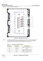
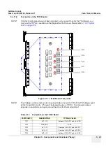
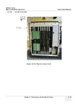
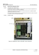
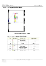
Test points on the TX128 board
NOTE:
If the test points below have not been mounted, and you want to verify the TX voltages, you
must use the TXP test, available via the Diagnostics Test Screen. Please refer to
.
NOTE:
The Voltages on these test points are approximately one tenth (1/10) of the TX Voltages used
by the transmitter circuits. (The exact [calculated] value is 10/101). The measured values
depends on selected scanning mode and the Acoustic Power adjustment.
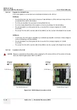
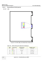
Figure 5-17 TX128 Board: Test points
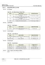
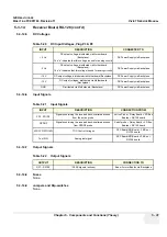
Table 5-13 Test points on the TX128 Board
TESTPOINT #
DESCRIPTION
TYPICAL VALUE
TP11
HV1+ /10
B0.25 VDC and +8.0 VDC
TP12
GROUND
0 VDC
TP13
HV1- /10
Between -0.25 VDC and -8.0 VDC
TP14
HV2- /10
Between -0.25 VDC and -4.0 VDC
TP15
HV2+ /10
B0.25 VDC and +4.0 VDC
TP12
TP14
TP15
TP11
TP13
Summary of Contents for Vivid 7
Page 1: ...GE Healthcare Operating Documentation Vivid 7 Service Manual Part Number FC091194 Revision 11...
Page 2: ......
Page 9: ...GE HEALTHCARE DIRECTION FC091194 REVISION 11 VIVID 7 SERVICE MANUAL vii JA ZH CN KO...
Page 38: ...GE HEALTHCARE DIRECTION FC091194 REVISION 11 VIVID 7 SERVICE MANUAL xxxvi...
Page 856: ...GE HEALTHCARE DIRECTION FC091194 REVISION 11 VIVID 7 SERVICE MANUAL Index 8...
Page 857: ......


