GE H
EALTHCARE
D
IRECTION
FC091194, R
EVISION
11
V
IVID
7 S
ERVICE
M
ANUAL
Chapter 5 - Components and Functions (Theory)
5 - 29
5-3-14
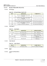
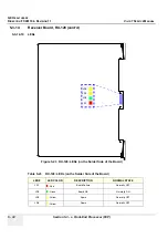
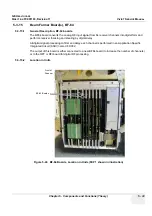
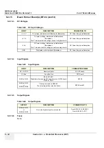
Receiver Board, RX-128
5-3-14-1
General Description
5-3-14-2
Signals From Active Probe
•
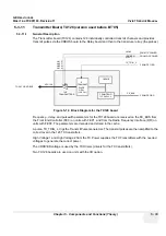
The RX-128 Board has 128 identical receive channels (XD1-XD128).
•
The signal in each channel is fed via a Transmit/Receive (T/R) switch to a preamplifier.
•
From the preamplifier the signal goes to a Time Controlled Gain (TGC) amplifier used to equalize
the signal strength from the near field, the mid field and the far field.
•
The output channels (RX1 - RX128) are then output via the backplane to the Beamformer boards.
Figure 5-21 RX128 Block Diagram
Demodulator
Mux
Analog
Beamformer
T/R
T/R
Relay
Prog
LP
Filter
Pedof
(CW mode)
(PW mode)
I
Q
12 Bit ADC
MLA0
MLA1
Rx[1:128]
Preamp
+
-
Buffer & Level
Test Signals
TGC Ctrl
XD[1:128]
Enable
Summary of Contents for Vivid 7
Page 1: ...GE Healthcare Operating Documentation Vivid 7 Service Manual Part Number FC091194 Revision 11...
Page 2: ......
Page 9: ...GE HEALTHCARE DIRECTION FC091194 REVISION 11 VIVID 7 SERVICE MANUAL vii JA ZH CN KO...
Page 38: ...GE HEALTHCARE DIRECTION FC091194 REVISION 11 VIVID 7 SERVICE MANUAL xxxvi...
Page 856: ...GE HEALTHCARE DIRECTION FC091194 REVISION 11 VIVID 7 SERVICE MANUAL Index 8...
Page 857: ......


