GE
D
IRECTION
FQ091019, R
EVISION
2
V
IVID Q
N S
ERVICE
M
ANUAL
8-58
Section 8-3 - Internal Component Replacement Procedures
4.) Gently pull the LCD display upwards and fully tighten the hinge screws on both the left and right
sides of the display.
5.) Re-connect the flex cable (indicated in
).
6.) Fit the display frame onto the AOU LCD Display and cover the securing screws with the screw-caps
provided.
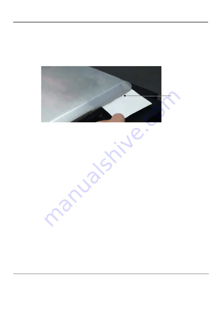
7.) Verify that the Vivid q N lid opens and closes freely and check that there is a “paper-thin” gap
between the top rear cover and the keyboard surface as shown in
.
8.) Fully tighten the hinge screws.
9.) Return the Keyboard Assembly to its location on the Bottom Assembly, as described in
Panel and Keyboard Installation Procedure" on page 8-12
10.)Refit the bearing handle, as described in the
"Bearing Handle Installation Procedure" on page 8-3
.
11) For the final stage of the LCD Display installation procedure, proceed to calibrate the
newly-installed LCD Display by making any adjustments required to the
Brightness
,
Contrast
and/or
Blue Tint,
as described in the
"LCD Display Adjustments and Calibration" on page 6-1
12.)Proceed to perform the following functionality tests:
-
"SafeLock Cart - Grounding Continuity" on page 10-22
- only if the Vivid q N system is
currently mounted on the SafeLock cart
-
"SafeLock Cart - Chassis Current Leakage Test" on page 10-24
-
"Full System Test" on page 7-10
NOTE:
In the event that the installed AUO LCD monitor flickers after installation, the DC Power Supply should
be replaced with a new DC Power Supply, P/N 5439596. Follow the instructions provided in the
"DC-to-DC Power Supply Replacement Procedure" on page 8-48
Figure 8-69 Checking the Gap Between the Vivid q NLid and the Bottom Assembly
Testing the Gap


