


GE H
EALTHCARE
RAFT
V
OLUSON
E8 / V
OLUSON
E6
D
IRECTION
KTD102576, R
EVISION
7
DRAFT (A
UGUST
23, 2012)
S
ERVICE
M
ANUAL
10-16
Section 10-7 - Electrical Safety Tests
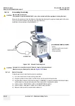
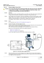
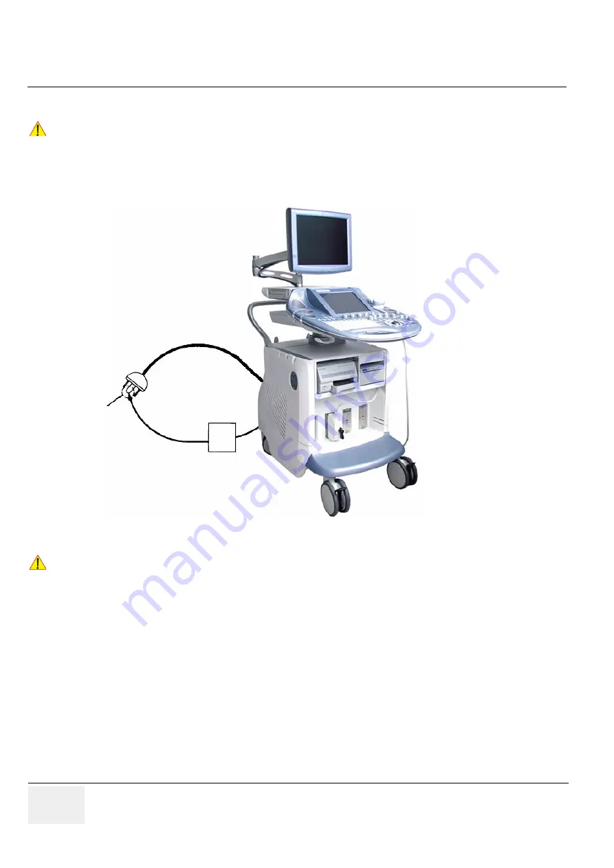
10-7-4
Grounding Continuity
Measure the resistance from the third pin of the attachment plug to the exposed metal parts of the case.
The ground wire resistance should be less than
0.2
ohms.
Reference the procedure in the IEC60601-1-1.
10-7-4-1
Meter Procedure
Follow these steps to test the Ground wire resistance.
1.) Turn the Voluson E8 / Voluson E6 system OFF.
2.) Plug the system into the meter, and the meter into the tested AC wall outlet.
3.) Plug the black chassis cable into the meter's “CHASSIS” connector and attach the black chassis
cable clamp to an exposed metal part of the Voluson E8 / Voluson E6 system.
4.) Set the meter’s “FUNCTION” switch to the RESISTANCE position.
5.) Set the meter's “POLARITY” switch to the OFF (center) position.
6.) Measure and record the Ground wire resistance.
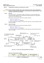
CAUTION
!! CAUTION:
Electric Shock Hazard!
The patient or operator MUST NOT come into contact with the equipment during this test
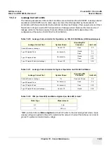
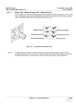
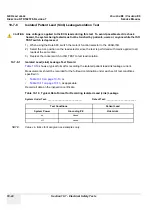
Figure 10-2 Ground Continuity Test
CAUTION
!! CAUTION:
Lacquer is an isolation barrier! Resistor may be high-impedance!
Measure only on blank parts, stated in
ACCESSIBLE METAL PARTS
GROUND PIN
OHMMETER
• Potential equilibrium connector
• Monitor housing
• Probe connector
such as:
Summary of Contents for Voluson E8
Page 2: ......
Page 11: ...GE HEALTHCARE VOLUSON E8 VOLUSON E6 DIRECTION KTD102576 REVISION 7 SERVICE MANUAL ix ZH CN KO...
Page 431: ......


