GE H
EALTHCARE
DRAFT
V
OLUSON
E8 / V
OLUSON
E6
D
IRECTION
KTD102576, R
EVISION
7
DRAFT (A
UGUST
23, 2012)
S
ERVICE
M
ANUAL
Chapter 8 - Replacement Procedures
8-27
Installation Procedure at systems WITH power connector
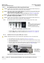
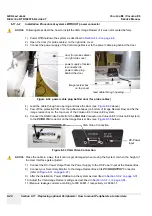
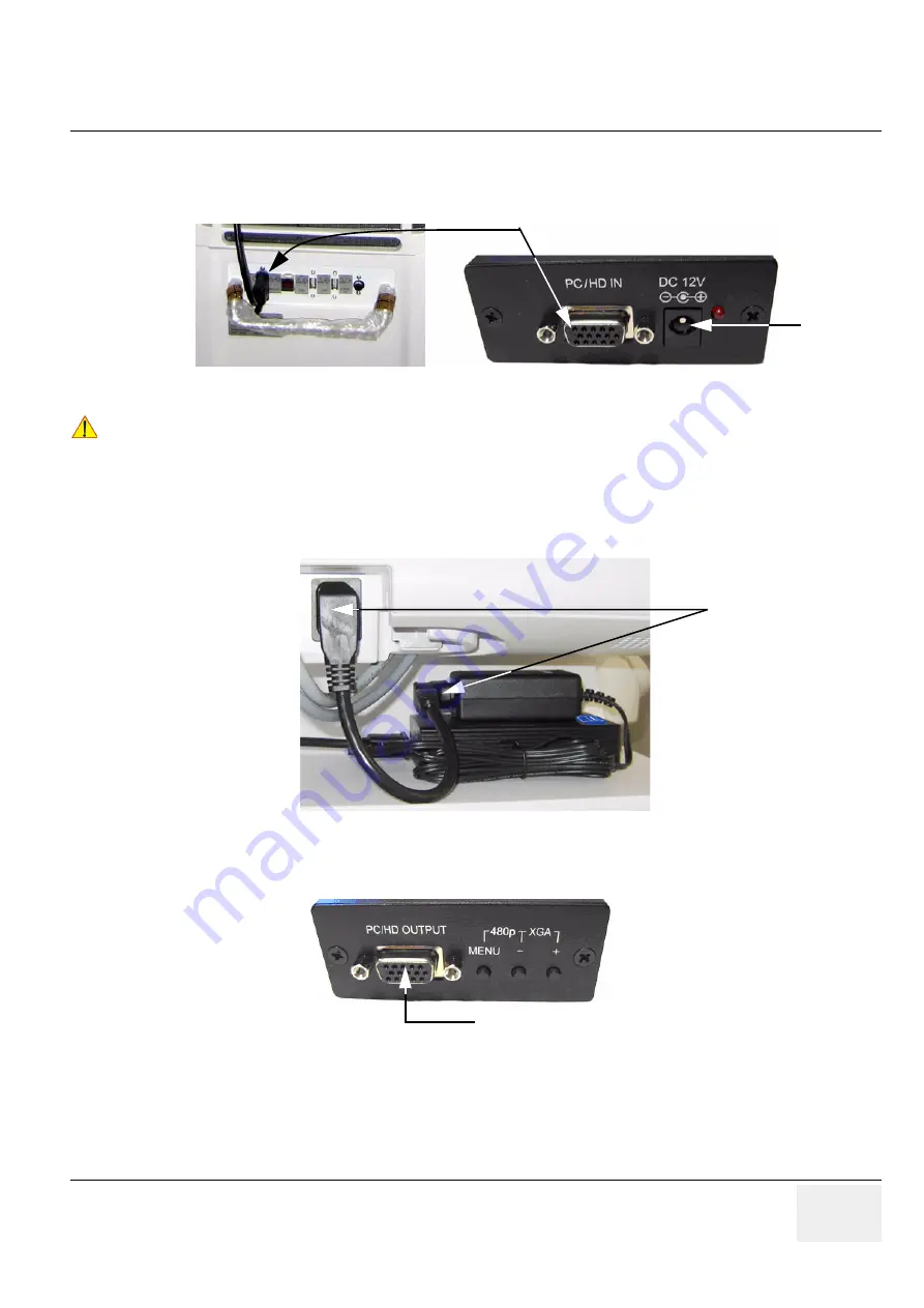
4.) Connect the RGB Video Cable from the
VGA Out
Connector (on Voluson E8 / Voluson E6 system)
to the
PC/HD IN
Connector on the Image Resizer Box (see:
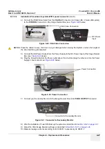
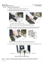
5.) Connect the DC-Power Output from the Power Supply to the DC-Power Input at the Image Resizer
above).
6.) Plug the Power Cable into the Power outlet above this shelf and plug the other end into the Power
Supply’s input socket (see:
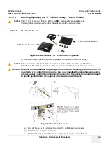
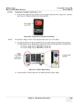
7.) Connect your Secondary Monitor to the Image Resizer Box at its
PC/HD OUTPUT
Connector.
8.) After the installation, Power ON/Boot up the system as described in
.
9.) Adjust the VGA Image Resizer settings as described in
10.)Measure leakage currents according to IEC 60601-1 respectively UL 60601-1.
Figure 8-29 VGA Video Connection
NOTICE
!! NOTICE:
Place the cable in a way, that it can not get damaged when moving the System or when the height of
the User Interface gets adjusted.
Figure 8-30 Power Connection
Figure 8-31 Connector for Secondary Monitor
VGA Video Connection
DC-Power
Input
Power Connection
Connector for Secondary Monitor
Summary of Contents for Voluson E8
Page 2: ......
Page 11: ...GE HEALTHCARE VOLUSON E8 VOLUSON E6 DIRECTION KTD102576 REVISION 7 SERVICE MANUAL ix ZH CN KO...
Page 431: ......


