GE H
EALTHCARE
RAFT
V
OLUSON
E8 / V
OLUSON
E6
D
IRECTION
KTD102576, R
EVISION
7
DRAFT (A
UGUST
23, 2012)
S
ERVICE
M
ANUAL
8-28
Section 8-17 - Replacing optional Peripherals / How to mount Peripherals at a later date
8-17-3-2
Installation Procedure at systems WITHOUT power connector
1.) Power Off/Shutdown the system as described in
.
2.) Open the door (for probe cables) on the right side cover.
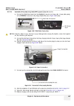
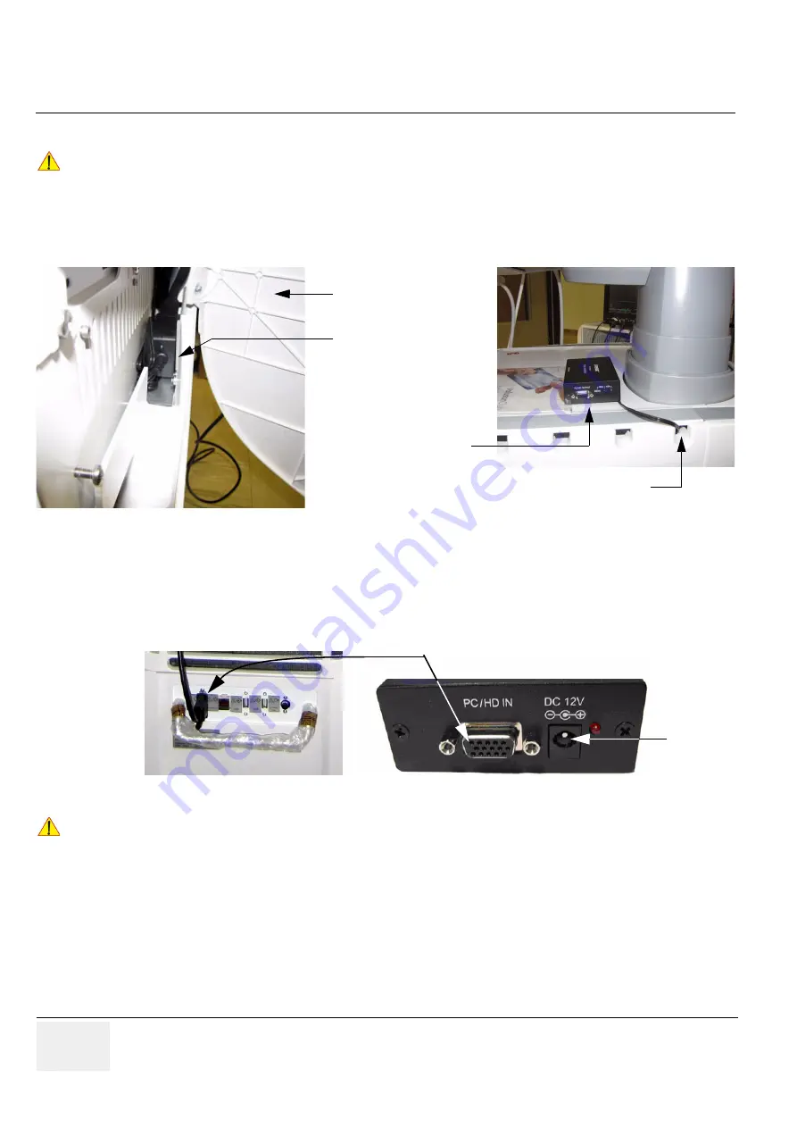
3.) Connect the power supply of the VGA Image Resizer to the power cable plug behind the door.
4.) Lead the cable through an opening and close the door (see:
above).
5.) Peel off the protective film from the adhesive tapes (on bottom of Image Resizer Box) and fix the
image resizer box on the top cover of the Voluson E8 / Voluson E6 system.
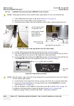
6.) Connect the RGB Video Cable from the
VGA Out
Connector (on Voluson E8 / Voluson E6 system)
to the
PC/HD IN
Connector on the Image Resizer Box (see:
7.) Connect the DC-Power Output from the Power Supply to the DC-Power Input at the Resizer Box.
8.) Connect your Secondary Monitor to the Image Resizer Box at its
PC/HD OUTPUT
Connector
).
9.) After the installation, Power ON/Boot up the system as described in
.
10.)Adjust the VGA Image Resizer settings as described in
11.)Measure leakage currents according to IEC 60601-1 respectively UL 60601-1.
NOTICE
!! NOTICE:
Following steps describe, how to install the VGA Image Resizer (if it was not mounted before).
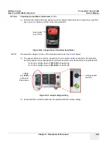
Figure 8-32 power cable plug behind door (for probe cables)
Figure 8-33 VGA Video Connection
NOTICE
!! NOTICE:
Place the cable in a way, that it can not get damaged when moving the System or when the height of
the User Interface gets adjusted.
image resizer box
lead cable through opening
door (for probe cables)
on right side cover
power supply of resizer
is connected to
power cable plug
behind the door
on top cover
VGA Video Connection
DC-Power
Input
Summary of Contents for Voluson E8
Page 2: ......
Page 11: ...GE HEALTHCARE VOLUSON E8 VOLUSON E6 DIRECTION KTD102576 REVISION 7 SERVICE MANUAL ix ZH CN KO...
Page 431: ......

