


GE
V
OLUSON
i / V
OLUSON
e
D
IRECTION
KTI106052, R
EVISION
10
S
ERVICE
M
ANUAL
8-42
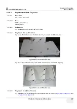
Section 8-18 - Replacement of the Modo Cart Components
8-18-3
Replacement of the Fuses
8-18-3-1
Manpower
One person, 10 minutes
8-18-3-2
Tools
Phillips screwdriver 1 and 2
8-18-3-3
Preparations
1.) Power Off/Shutdown the system as described in
Section 3-6-3 on page 3-72
8-18-3-4
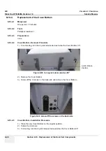
Fuses - Removal Procedure
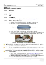
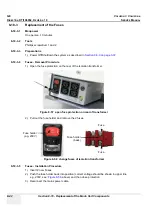
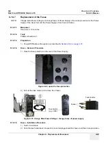
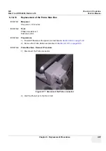
1.) Open the fuse protection on the rear of the isolation transformer.
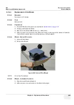
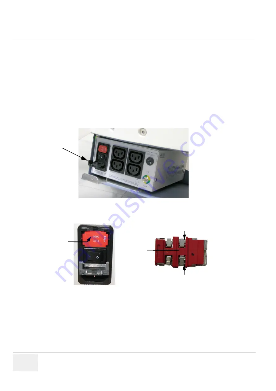
2.) Pull out the fuse holder and remove the 2 fuses.
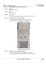
8-18-3-5
Fuses - Installation Procedure
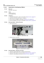
1.) Insert 2 new Fuses.
2.) Push the fuse holder back into position (correct voltage should be shown in upper line
e.g, 230V, see:
Figure 8-58
, above) and then close protection.
3.) Reconnect the mains power cable.
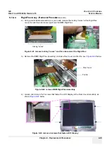
Figure 8-57 open fuse protection on rear of transformer
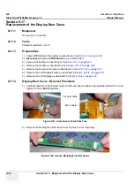
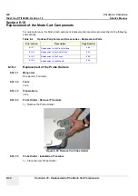
Figure 8-58 change fuses of isolation transformer
Fuse holder
(e.g. 230V)
Fuse
Fuse
Fuse holder
(back)
Summary of Contents for Voluson i BT06
Page 2: ......
Page 11: ...GE VOLUSON i VOLUSON e DIRECTION KTI106052 REVISION 10 SERVICE MANUAL ix ZH CN KO...
Page 44: ...GE VOLUSON i VOLUSON e DIRECTION KTI106052 REVISION 10 SERVICE MANUAL xlii Table of Contents...
Page 514: ...GE VOLUSON i VOLUSON e DIRECTION KTI106052 REVISION 10 SERVICE MANUAL IV Index...
Page 515: ......


