background image

– 2 –

IMPORTANT SAFETY NOTICE

The  information  in  this  service  guide  is  intended  for  use  by 

individuals  possessing  adequate  backgrounds  of  electrical, 

electronic,  and  mechanical  experience.  Any  attempt  to  repair  a 

major  appliance  may  result  in  personal  injury  and  property  

damage.  The  manufacturer  or  seller  cannot  be  responsible  for  the 

interpretation  of  this  information,  nor  can  it  assume  any  liability  in 

connection with its use.

CAUTION

To  avoid  personal  injury,  disconnect  power  before  servicing 

this  product.  If  electrical  power  is  required  for  diagnosis  or  test  

purposes,  disconnect  the  power  immediately  after  performing  the 

necessary checks.

RECONNECT ALL GROUNDING DEVICES

If  grounding  wires,  screws,  straps,  clips,  nuts,  or  washers  used  to 

complete  a  path  to  ground  are  removed  for  service,  they  must  be 

returned to their original position and properly fastened.

GE Consumer & Industrial

Technical Service Guide

Copyright © 2006

All rights reserved. This service guide may not be reproduced in whole or in part 
in any form without written permission from the General Electric Company.

Summary of Contents for WCCB1030HWC

Page 1: ...31 9165 GE Coin Operated Washers Technical Service Guide August 2007 GE Consumer Industrial WCCB1030HWC WCCB2050HWC WCRD2050HWC WMCD2050HWC ...

Page 2: ... avoid personal injury disconnect power before servicing this product If electrical power is required for diagnosis or test purposes disconnect the power immediately after performing the necessary checks RECONNECT ALL GROUNDING DEVICES If grounding wires screws straps clips nuts or washers used to complete a path to ground are removed for service they must be returned to their original position an...

Page 3: ...rain Pump 19 Harness Fuse 22 Installation Instructions 7 Inverter Motor 21 Inverter Motor Signal LED 28 Inverter Motor Test 29 Mode Shifter Coil Test 29 Motor and Drive System 15 Rating Plate Mini Manual Location 4 Shaft and Mode Shifter Assembly 25 Shaft and Mode Shifter Overview 16 Spin Basket 14 Timer 11 Tub Assembly 23 Tub Cover 23 Water Usage 13 ...

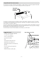
Page 4: ...tive service The mini manual is located in the backsplash and contains service information MINI MANUAL LOCATION Rating Plate at rear of backsplash Rating Plate and Mini Manual Location The rating plate containing model and serial number is located on the rear of the control panel in the center If you lean over the washer you can see the rating plate without moving the unit Suggested Tool List 2 Ph...

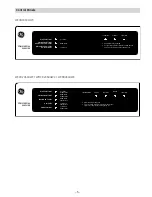
Page 5: ...TONS REGULAR PERM PRESS WHITE COTTONS COMMERCIAL WASHER DELICATES PERM PRESS MIXED LOADS HOT WASH NORMAL FAST 1 Read instructions under lid 2 For your saftey washer will not run with lid open Cycle is not complete until ALL lights go out FILLING WASHING TIME REMAINING RINSING FINAL SPIN WARM WASH NORMAL FAST WARM WASH GENTLE FAST COLD WASH GENTLE FAST COLD WASH NORMAL FAST PERMANENT PRESS COLORED ...

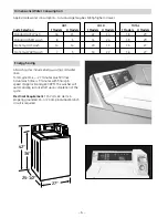
Page 6: ...inutes with final spin speed of approximately 630 RPM The washer will automatically turn itself off upon completion of the cycle Electrical Requirement 115 Volts 60 Hertz A properly grounded 15 or 20 amp individual branch circuit is required HOT COLD TOTAL Cycle Selection F Models H Models F Models H Models F Models H Models Standard HOT Wash 16 15 22 14 38 29 Standard WARM wash 8 5 31 24 39 29 Eco...

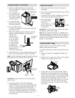
Page 7: ...nd left hose to COLD faucet Couplings should be hand tightened plus 1 2 turn with pliers Install Drain Nozzle 1 Insert one end of aluminum drain nozzle into standpipe 2 Slip or cut wire wrap back approximately 2 below top of standpipe 3 Cut drain hose just below standpipe Place silver hose clamp over black drain hose end 4 Insert drain nozzle into end of drain hose and position clamp to secure dra...

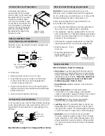
Page 8: ...z and connected to an individual properly grounded branch circuit protected by a 15 or 20 amp circuit breaker or time delay fuse If the electric supply provided does not meet the above specifications call a licensed electrician Water pressure 20 psi minimum Water temperature from water heater 120 to 150 F 50 to 66 C Note to Installer After Installation check the following Drain Hose must be pulled ...

Page 9: ...ring pump down prior to spin the turbo pump is energized and water is drawn out the sides and down through the self cleaning filter to clean and remove lint from the bottom side of the filter area and flush lint down the drain Energy Saving All wash cycles include energy saving cold water rinse Total Cycle Time 27 minute wash cycle plus fill time Wash time is 9 minutes with a final spin speed of approx...

Page 10: ...fit the correct mating connector Control panel is galvanized with three tabs designed to allow the switchtrim to be supported during service Mini Manual is located in the control panel 1 Remove four 4 T20H Torx screws from the top of control panel as shown Mini Manual can be accessed from this position as illustrated 2 Water valve is serviceable by removing the 4 T20H Torx screws from the top of th...

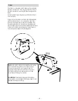
Page 11: ...CH CAN BE ACCESSED BY REMOVING DOOR AND LATCH ASSEMBLY ON METER CASE AS SHOWN USING A PLASTIC PEN TO PREVENT SHOCK HAZARD HOLD DOWN LID SWITCH ACTIVATOR AND THIS WILL ALLOW YOU TO RUN THE MACHINE WITH LID UP FOR SERVICE WARNING TAKE NECESSARY PERSONAL SAFETY PRECAUTIONS TO AVOID PERSONAL INJURY DUE TO SPIN BASKET RUNNING WITH LID UP DUST COVER MOTOR SWITCH LOCATING BOSS TIMER IN COIN BOX Note Lid ...

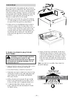
Page 12: ...he washer To Service Front Panel 1 Locate the two spring clips between cover and front panel and cover 2 Insert putty knife and push to release clips 3 Rotate front panel forward and lift off cabinet base locating tabs 4 To reassemble place front panel on washer base locating tabs rotate up into place and press top of panel at clips until panel snaps into place To Service Cover Lid Assembly 1 Remo...

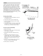
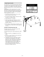
Page 13: ...tch bracket to remove 5 Reverse steps to reassemble put machine in spin for at least one minute before checking operation of switch ECONOMY WATER SAVER SETTING The pressure switch is set in the factory for the medium water level and usage To Change setting from medium water level to high or low 1 Make sure washer is unplugged from electrical outlet 2 Remove 4 screws from top of control panel and l...

Page 14: ...smission spline shaft Tech Tip The 7 16 bolt has an O ring and should be replaced every time it is removed to maintain air bell seal 6 Remove left handed 1 11 16 transmission hub nut This nut is aluminum take care not to round the edges when removing or replacing Note that the word LOOSEN with an arrow show ing turn to the LEFT appears on the nut 7 Lift tub basket platform forward to allow clear a...

Page 15: ...n is for information only The motor is bi directional constantly reversing it s direction to provide agitation The motor is connected by a belt to the shaft and mode shifter assembly By energizing or de energizing a coil the mode shifter assembly engages or disengages the shaft and tube This allows for agitation and spin cycle modes Motor status is displayed through a series of flash codes from a g...

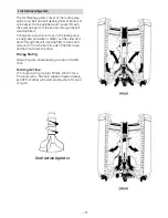
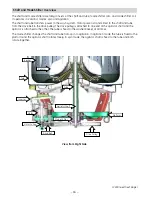
Page 16: ...e drive pulley is attached to one end of the agitator shaft and the agitator is attached to the other The tube is fixed to the washer basket at all times The mode shifter changes the shaft and tube from spin to agitation In agitation mode the tube is fixed to the platform and the agitator shaft rotates freely In spin mode the agitator shaft is fixed to the tube and both rotate together Basket Motor A...

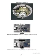
Page 17: ... Mode Shifter Cam Mode Shifter Coil Drive Pulley Mode Shifter Cam Continued next page Drive Shaft Note Mode shifter coil energized for agitate mode cam teeth disengaged from drive pulley Shaft and Mode Shifter Assembly Note Mode shifter coil de energized for spin idle mode cam teeth engaged in drive pulley ...

Page 18: ...the remainder of the agitation cycle The inverter motor controls the speed of agitation The agitator stroke rate is approximately 30 strokes per minute This rate is the same for all cycles The speed of the motor controls the arc At fast speed the arc is approximately 360 degrees At slower speeds the arc is substantially less It is the distance of the arc that determines normal or gentle wash cycle...

Page 19: ...ie after step 7 Disconnect power Remove the front panel See Front Panel Center belt on drive pulley and secure tightly with wire tie as shown on following page Align wire tie as shown Stretch the belt install tool to fit over the end of the motor shaft See Figure A Slide belt install tool upward until it snaps into the first groove of the motor shaft See Figure B Center belt on motor shaft grooves a...

Page 20: ...t will be slightly smaller than the drive pulley A belt that has been installed on the drive pulley will stretch to the diameter of the pulley over time This is normal and does not indicate a bad belt New Belt on Pulley ...

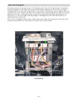
Page 21: ...washer will still fill with water count down on the display and drain If during an agitation cycle water leaks from the tub and resets the pressure switch the inverter control stops agitation and goes through the mode shifter spin program to de energize the cam and the washer starts to refill with water The motor will not run again until the pressure switch is satisfied at which time the inverter con...

Page 22: ...rm before tightening motor nuts There could be one or two alignment pins 7 8 9 Alignment Pin Pin Locator Hole Note When replacing a motor check its brake operation Place washer in a spin cycle and lift the lid after it has reached full speed The basket should stop within 7 seconds If time exceeds 7 seconds check the lid switch operation and check the belt for worn ribs or slippage due to residue o...

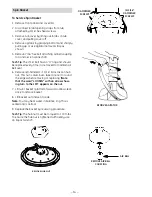
Page 23: ...over Tub Assembly Note The motor can be replaced without removing the tub See Inverter Motor The tub assembly must be removed when replacing the spin basket outer tub or certain speed drive components To remove the tub assembly Disconnect power Lower the drain hose into a small bucket to remove any water remaining in the tub Remove the front panel See Front Panel Remove the cover lid assembly See ...

Page 24: ...ter tub Pinch off the black sump hose to prevent water spills Loosen the 5 16 screw type hose clamp and remove the sump hose at the tub 12 13 14 Disconnect Platform Ground Wire WARNING Exposed terminals inverter board and rotating parts may cause injury and or electrical shock To reduce the risk of electrical shock disconnect power and allow at least 30 seconds for capacitors to discharge before s...

Page 25: ...semblies by raising the tub and removing the spring assemblies from the platform 15 Remove the tub assembly from the cabinet and place it on a protected surface 18 Shaft and Mode Shifter Assembly The shaft and mode shifter assembly consists of the shaft and tube mode shifter cam and mode shifter coil These parts come only as an assembly WARNING Do not attempt to disassemble the shaft and mode shif...

Page 26: ...ab that attaches the mode shifter coil wire harness retainer to the front of the platform 4 5 Center Core of Pulley Note When replacing pulley tighten pulley nut to 275 in lbs of torque Note In the following step after removing the pulley nut it may be helpful to grab the center core of the drive pulley with one hand and gently tap one of the drive pulley arms with a hammer The drive pulley will p...

Page 27: ... from the bottom of the platform 8 Remove the four 1 2 hex head bolts that attach the platform to the tub 9 Place the platform upright on a protected surface and remove the tub bearing washer from the tube 11 Lift the platform from the tub 10 Tub Bearing Washer ...

Page 28: ...an be viewed for diagnostic testing It is best viewed from the right side of the motor When Motor is operating normally and running the LED blinks at a constant rate of 1 2 second on and 1 2 second off When Motor is operating normally and idle the LED blinks at a constant rate of 1 second on and 1 second off Motor control error condition LED is on for 25 seconds and off for 25 seconds for a specifi...

Page 29: ... for approximately 15 seconds at the beginning of the agitate program 30 VDC is present during the remainder of the agitate cycle Note All electrical testing is done at harness plug Mode Shifter Coil Test Note The mode shift coil connects to C7 connector on inverter motor assembly Unplug C7 connector and check continuity Mode shift coil resistance value is approximately 98Ω room temperature 77 F C...

Page 30: ...s at a rate of second on and second off for the remainder of the 6 second period The motor continues to operate with this error When a locked rotor is detected the washer will sit idle for 15 seconds and retry If the motor does not operate after 3 tries the LED will blink 6 times at a rate of second on and second off for the remain der of the 6 second period When a lid switch error is detected by ...

Page 31: ...onds after lid is lifted If the tub takes approximately 10 seconds to stop check drive belt for wear If tub coasts to stop brake resistor has failed and inverter motor assembly must be replaced If the tub takes longer than 25 seconds to stop the inverter will initiate a long brake time error code See Inverter Motor Error Codes ...

Page 32: ... 32 GE Consumer Industrial Appliances General Electric Company Louisville KY 40225 ge com N D 07E 2227 ...

Reviews: