background image

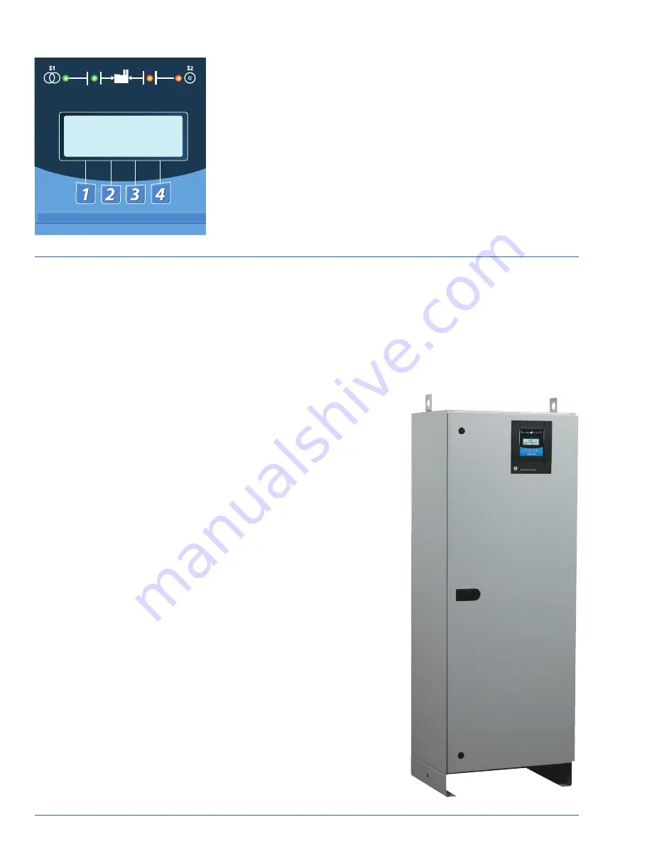
Enhanced Display and Settings

LED

s are used in a recognizable line configuration for continuous monitoring of switch

position. The LCD display shows source availability, exercise time delay operation and
system source condition. A simplified adjustment is featured for voltage, frequency and
time delay settings.

The control operates off a close differential 3-phase under-voltage sensing of Source 1,
factory standard setting 90% pickup, 80% dropout; under-frequency sensing of Source 1
factory setting 95% pickup; 3-phase voltage and frequency sensing of Source 2, factory
standard setting 90% pickup voltage, 95% pickup frequency. All factory settings are
operator adjustable.

A test function is standard (fast test/load/no load) to simulate Source 1 failure - 
automatically bypassed should Source 2 fail.

Entelli-Switch 250


M O R E

L O A D   D I S C O N N E C T   T D

P R E   X F R

T I M E   R E M A I N I N G   0 4 : 0 2

MX

250 Series Microprocessor Controller

PB

-5066

Page 4

More Enhanced Features

• Available in all transfer modes:

~ Open, Delayed & Bypass/Isolation

~ Closed (with newly integrated

transition control)

• User-friendly programmable engine

exerciser, used for the engine gen-
erator with or without load, at any
interval in a one-year period

Controller can be configured

to any voltages for worldwide

application

• Real-time display of ATS status,

including active timer(s)

• Multiple levels of user-defined

password protection

• Serial communications allowing

connectivity with other ATS's,
paralleling switchgear, and
SCADA

systems

• Time-tested synchronous logic

automatically measures phase
angle and frequency allowing
disturbance-free transfer

• Unsurpassed statistical ATS/System

monitoring available in real-time

• T3/W3 elevator pre-signal.

Automatically bypassed if the
selected source fails, minimizing
time an elevator is without power

• Universal Motor Disconnect (UMD)

sends a pre-signal, post-signal or
both to any motor control center.
Not bypassed in an outage, the
UMD

ensures safety in the event

of a single phase loss

• Voltage unbalance detection

standard

• Extensive 2/5/10 Warranty

Technical Benefits

• Separate line voltage components

for controller isolation

• Inputs optoisolated for high electrical

immunity to transients and noise

• Built-in electrical operator protection

• Simplified maintenance – major

components are easily replaceable

• Close differential under-voltage

sensing of the normal source

• Voltage and frequency sensing

of the emergency source
(all settings are adjustable)

Performance Features

• UL, CSA and IEC listed

• Ringing wave immunity per IEEE

472 (ANSI C37.90A)

• Conducted and Radiated Emissions

per EN55022 Class B

(CISPR 11) (Exceeds EN55011 &
MILSTD

461 Class 3)

• ESD Immunity test per EN61000-4-2

Class B (Level 4)

• Radiated RF, electromagnetic

field immunity test per
EN

61000-4-3 (ENV50140) 10v/m

• Electrical fast transient/burst 

immunity test for EN61000-4-4

• Surge immunity test per

EN

61000-4-5 (IEEE C62.41)

(1.2 x 50μs, 0.5 to 4 kV)

• Conducted immunity test per

EN

61000-4-6 (ENV50141)

• Voltage dips and interruption


immunity EN

55011 :2009+A1 :2010

Summary of Contents for Zenith ZTS Series

Page 1: ...GE Digital Energy Power Quality Zenith ZTS Series Low Voltage Automatic and Manual Transfer Switches ...

Page 2: ...ed Transition Bypass Switches 100 4000 Amps All ZTS products meet or exceed industry requirements allowing specification and installation confidence UL 1008 listed through 480 VAC CSA C22 2 No 178 listed through 600 VAC IEC 947 6 1 listed through 480 VAC Codes and Standards NFPA 70 99 101 110 IEEE 446 241 602 NEC 517 700 701 702 NEMA ICS 10 Controls tested in accordance with IEEE 472 ANSI C37 90A EN...

Page 3: ...ounted on a specially formed panel Logic devices including microprocessor control auxiliary time delays and special accessory equipment are assembled on the door for ease of maintenance and separation from the power section They are connected with a numbered wiring harness equipped with a disconnect plug that allows isolation of the control panel for maintenance ZTS Series Method of Operation When...

Page 4: ...ommunications allowing connectivity with other ATS s paralleling switchgear and SCADA systems Time tested synchronous logic automatically measures phase angle and frequency allowing disturbance free transfer Unsurpassed statistical ATS System monitoring available in real time T3 W3 elevator pre signal Automatically bypassed if the selected source fails minimizing time an elevator is without power ...

Page 5: ...es and need to be specified AB3 Auxiliary Contact closed in bypass emergency Source 2 S P D T Standard up to 400A Additional available 10 max on ZBTS Series and need to be specified AB4 Auxiliary Contact closed in bypass normal Source 1 S P D T Standard up to 400A Additional available 10 max on ZBTS Series and need to be specified CALIBRATE Microprocessor activated calibration feature CDP Programm...

Page 6: ... 1 R1 3 Over Voltage sensing for normal Source 1 single R1 1 or three R1 3 phase R15 R15D Load Shed Should Source 2 become overloaded an external signal can be given to ATS to transfer to the Neutral or dead Normal Source 1 position R16 Phase rotation sensing of Normal Source 1 and Emergency Source 2 R50 In Phase monitor between Normal Source 1 and Emergency Source 2 to allow transfer S5P Micropro...

Page 7: ...14 HxWxD For 260 400A the enclosure is 66 x 24 x 19 75 HxWxD For 600A the enclosure is 74 x 40 x 19 75 HxWxD For certified drawings please contact the GE factory Application Notes NOTES Line and load terminals are located in rear and arranged for bus bar connection Terminal lugs are available as an accessory Contact the GE factory for more details 1 Special terminal lugs and neutral bars are availa...

Page 8: ...0 1 3 wire 50 5 7 480 1 2 wire 60 5 8 254 440 3 4 wire 60 6 0 575 3 3 wire 60 6 1 347 600 3 4 wire 60 6 3 575 1 2 wire 60 7 0 277 480 3 4 wire 60 7 1 277 1 2 wire 60 7 4 266 460 3 4 wire 60 7 5 460 3 3 wire 60 8 2 380 1 2 wire 50 9 0 240 416 3 4 wire 60 9 1 220 380 3 4 wire 60 9 2 220 380 3 4 wire 50 9 3 240 416 3 4 wire 50 9 7 380 3 3 wire 60 Note Operating voltage must be specified at time of or...

Reviews: