
36" and 48" GAS RANGETOPS
36" Natural Gas Models: ZGU364NDP, ZGU364NRP,
ZGU366NP
36" LP Gas Models: ZGU364LDP, ZGU364LRP, ZGU366LP
48" Natural Gas Models: ZGU484NGP, ZGU486NDP,
ZGU486NRP
48" LP Gas Models: ZGU484LGP, ZGU486LDP,
ZGU486LRP
IMPORTANT NOTICE: This information is intended for use
by persons possessing adequate backgrounds of electrical,
electronic, gas and mechanical experience. Any attempt to repair
a major appliance may result in personal injury and property
damage. The manufacturer or seller cannot be responsible
for the interpretation of this information, nor can it assume
any liability in connection with its use.
WARNING:
DISCONNECT POWER BEFORE SERVICING
Disconnect the rangetop electrical power supply at the household
distribution panel by removing the fuse or switching off the circuit
breaker.
Shut off the gas supply in the gas line by closing the manual
shut-off valve.
Shut off the rangetop gas supply by closing the rangetop shut-off
valve located beneath the rangetop.
IMPORTANT: Reconnect all grounding devices. All parts of this
appliance capable of conducting electrical current are grounded.
If grounding wires, screws, straps, clips, nuts or washers used
to complete a path to ground are removed for service, they must
be returned to their original positions and properly fastened.
CAUTION
—
The rangetop, as shipped from
the factory, is set for use with its intended gas. If you wish
to use your rangetop with the alternate gas, you must first
replace the orifices and convert the pressure regulator.
GAS CONVERSION KIT
The gas conversion kit is located inside the rangetop insulation
cover.
HIGH ALTITUDE KIT
For operation from 3,000 to 7,000 feet, order WB28K10553
Conversion Kit. This kit includes orifices for both LP and Natural gas
operation.
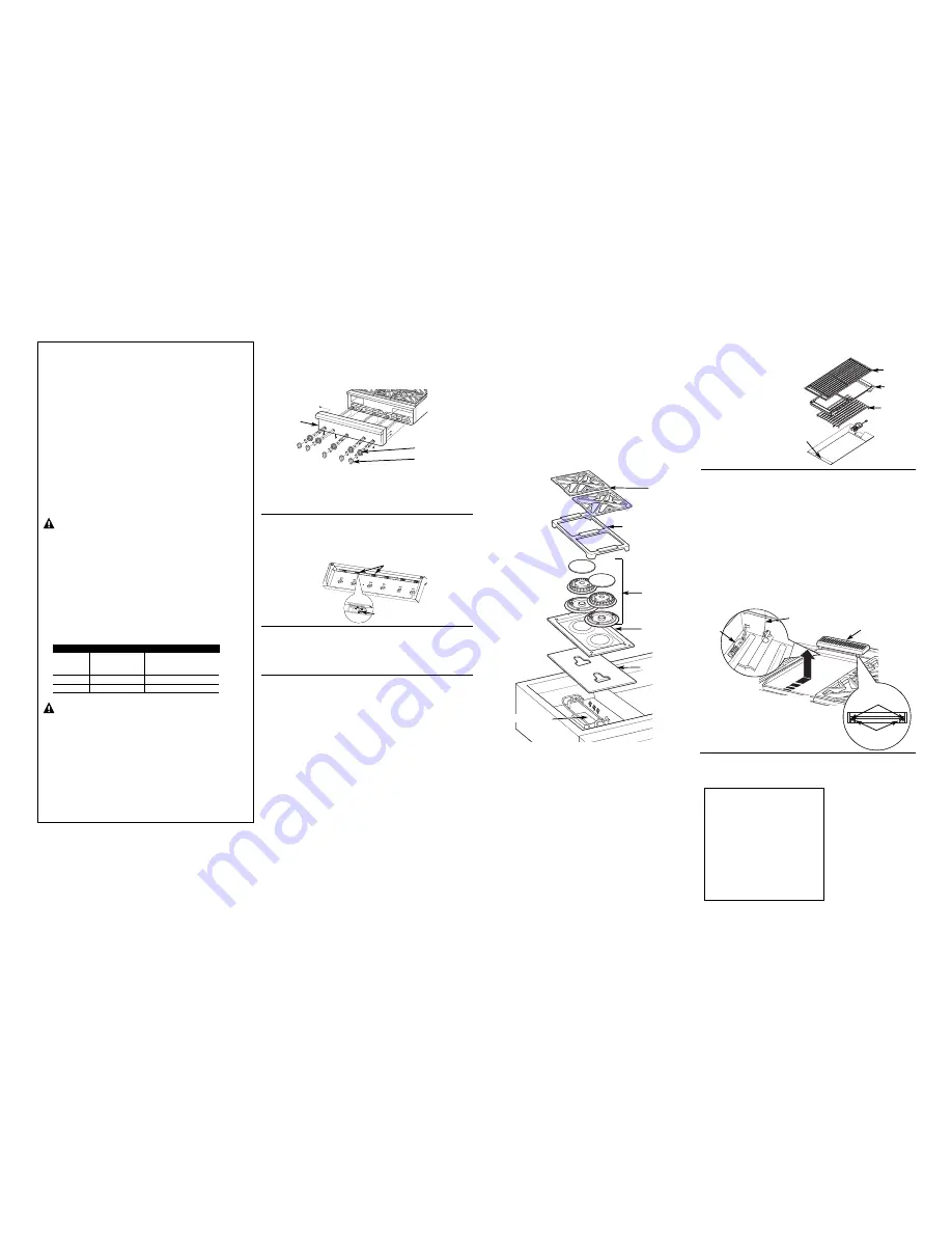
CONTROL PANEL REMOVAL
Slide the rangetop forward about 4". Pull the surface knobs off
and remove the screws from each bezel. Remove the screws from
the control panel face.
Remove the screws from the bottom of the control panel and from
the top (inside flanges, on each side, on the back side of the panel).
Remove the screws from the rear face of the control panel on
each side.
ACCENT LIGHTING REPLACEMENT
Remove the control panel. See the CONTROL PANEL REMOVAL
section.
Loosen the accent lighting module’s screw, slide out and replace.
SURFACE KNOB INDICATOR LIGHT REPLACEMENT
Remove the control panel. See the CONTROL PANEL REMOVAL
section. Find the indicator light on top of the gas valve, remove
the attached screw and replace.
GAS MANIFOLD AND VALVES REPLACEMENT
Refer to the Service Manual for replacement procedure.
SPARK MODULE REPLACEMENT
1.
Slide the rangetop forward about 4".
2.
Remove the control panel. See the CONTROL PANEL REMOVAL
section.
3.
Remove the screws from the rear trim and the left side trim.
All screws are on the inside, facing the burners.
4.
Remove the left grates and left grate frame. Remove surface
burners by removing all screws, but keep the outside burner
screws separate from the inside burner screws so they can
be easily replaced. Remove the burner pan, burner insulation
and spark module cover. Disconnect the igniter wires by pulling
them off of the connector pins.
GRILL IGNITER REPLACEMENT
Remove the grill cover, grate,
grate frame and radiant baffle.
Remove the screws from each
side of the pan surround and
remove the pan surround.
Remove the screws from
the igniter and pull the igniter
connector from the opening.
Disconnect the connector pin
and replace the igniter. Push
the igniter connector back
into the opening and replace
all parts.
GRIDDLE IGNITER REPLACEMENT
Lift off the griddle flue cover. Remove the 2 inside clamping screws.
NOTE:
Remove the 2 screws positioned on the inside only. Do not remove
the outermost screws—they are for leveling the griddle.
Slide the griddle toward the rear and out of the hold-down tabs along
the bottom front.
CAREFULLY lift and hold the griddle. A thermostat capillary is routed
through a clip. Gently lift the griddle to one side and slip the capillary out
of the clip. Do not disconnect or pull on the capillary. Gently lay the griddle
aside.
Remove the 2 burner hold-down screws at the rear of the burner
to loosen the burner. Remove the screws attaching the igniter. Pull
the igniter connector from the opening, disconnect the pin connection
and replace the igniter. Route the capillary back into the clip. Push
the excess capillary back through the opening. Push the igniter
connector back into the opening and replace all parts.
GRIDDLE HIGH LIMIT SWITCH
This switch is located at the front of the griddle box inside the burner box.
Refer to the Service Manual for further information.
INCOMING
GAS TYPE
PRESSURE TO
PRESSURE
REGULATOR
REGULATOR OUTPUT
Natural
6.0
″
to 14.0
″
W.C.P.
5.0
″
W.C.P.
L.P.
11
″
to 14
″
W.C.P.
10.0
″
W.C.P.
GAS SUPPLY REQUIREMENTS
Control Panel
Bezels
Surface Knobs
Grates
Grate Frame
Surface Burners
Spark Module Cover
Burner Pan
Burner Insulation
Grill Grate
Grill Grate
Frame
Radiant
Baffle
Pan
Surround
Griddle Flue Cover
Capillary
Igniter
Leveling Screws
Clamping Screws
Slide back griddle
and lift front
MODELNUMBERS
ZGU364NDP
, Z
GU364NRP
, Z
GU366NP
ZGU364LDP
, Z
GU364LRP
, Z
GU366LP
ZGU484NGP
, Z
GU486NDP
, Z
GU486NRP
ZGU484L
GP
, Z
GU486LDP
, Z
GU486LRP
IMP
OR
TANT
SERVICE
INFORMA
TION
DO
NO
T
DISCARD
31-14752
04-08
JR
Printed
in
Mexico
TAPE
ARE
A
Set Screw
Loosen


