38
D
GB
F
E
I
96463-08.2019-DGbFEIRu
8
|
Accessories
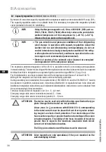
8.1 Capacity regulation
(
retrofit kit item no. 81443)
By means of one or two capacity regulators the compressor output can be reduced to 66 % resp. 33 %.
The capacity regulation works on a cylinder bank. It is necessary to replace the respective cylinder
cover (included in the kit) for retrofitting.
INFO
The gas velocities and pressure conditions of the refrigerating
plant change in operation with capacity regulation: Adapt the
suction line run and dimensioning correspondingly, do not set
control intervals too closely (steady state condition of the refrig-
eration plant must be reached), continuous operation in the con-
trol stage is not recommended (uneconomical).
Electrical control of the solenoid valve: Opened de-energized
(corresponds to 100 % compressor output).
ATTENTION
The device may be used only within the data specified on the type
plate. Changes to the device are not permitted.
A fuse (max. 3 x l
B
accordance with IEC 60127-2-1) corresponding
to the rated current must be placed in front of every valve actuat-
ing magnet as short-circuit protection. The rated voltage of the
fuse must be equal to or greater than the rated voltage of the valve
actuation magnets. The ability of the fuses to switch off must be
greater than or equal to the maximum assumable short-circuit
current at the installation location.
The EC type examination certifications must be observed.
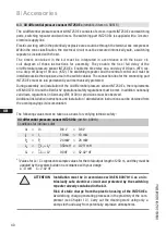
ATTENTION Valve magnets are only operational, if they are mounted on the
valve belonging to them.
INFO
Using the Norgren magnetic coil, ID no. 4280/4281 (GEA part no.
70123, 70124, 70125, 70149) effectively reduces the permissible
ambient temperature of the compressor to (−20 °C)–(+50 °C).
Observe the type plate on the magnetic coil.
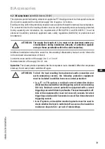
The explosion-protected magnetic coil for LR 12 is available in the Ex e mb design (encapsulation,
increased safety). The electrical wiring within the explosion risk area has to be carried out via a separate
terminal box that is designed in an approved ignition protection type M20 x 1.5 (e.g. Ex e).
For the installation, use heat-resistant lines with a temperature resistance of at least 140 °C.
Wiring of the magnetic coil has to be static and mechanically protected.
During assembly and installation, the requirements of EN 60079-14 and the EN 60079-17 have to
be observed. In addition, national laws, instructions (BetrSichV) or regulations have to be observed.
Additional installation instructions and installation/deinstallation instructions can be obtained from
the accompanying kit documentation.
Terminal cross-section of magnetic coil: 3 x 1.5 - 4.0 mm
2
.
Clamping range cable screw connections (metal): 5 - 8 mm.
Clamping range cable screw connections (plastic): 6 - 12 mm.

