background image

8

 D
 GB
 F
 E
 I

96463-08.2019-DGbFEIRu

2

|

 Product description

2.2  Ignition protection concept

In  accordance  with  Directive  2014/34/EU,  GEA  ATEX  compressors  are  suitable  for  use  in  device 


category 2 for explosive gas atmospheres up to temperature class T3 and explosion hazard subgroup
IIB 

/


IIC.

The entire compressor, including motor, is perceived as technically tight and therefore does not need 
an ignition protection.

To prevent ignition risk caused by working materials also during system malfunctions, all used work-

ing materials have to meet the requirements for the temperature class of the compressor. The surface 

temperature of the compressor may not exceed 80 % of the ignition temperature of the working 

material. For this reason all working materials need to have an auto-ignition temperature of > 250 °C.

To protect against high temperatures that may occur during incorrect operation or faults at the com-
pressor, the areas with the highest heat potential are controlled with temperature sensors (Ex b).  
The installation of the electronic control unit INT69 EX2 and the safety barrier, 
both included in the scope of supply, is therefore absolutely necessary.

The connection areas for load circuits are designed according to the requirements of the appliance 

category in Ex e. The circuits for the temperature sensors of the used ignition source control Ex b have
to be intrinsically safe to prevent inadmissibly high thermal or electric values. To ensure the intrinsic 
safety, the included safety barrier has to additionally be integrated in the electric circuit according to 
this assembly instruction.  The terminal board is designed for the protection type Ex de. The whole 

electric connection area is protected by a housing that complies with the requirements for the protec

-

tion type increased safety (Ex e).

The scope of delivery of the standard compressor comprises a conductive paint finish, that is suitable 
for the use in explosion group IIC. If the compressor is delivered with the accessory "Offshore Paint 
Finish", the application is restricted to explosion group IIB.

Summary of Contents for EX-HG66e Series

Page 1: ... 4 HC EX HG66e 1540 4 EX HGX66e 1540 4 EX HG66e 1540 4 HC EX HG66e 1750 4 EX HGX66e 1750 4 EX HG66e 1750 4 HC EX HG66e 2070 4 EX HGX66e 2070 4 EX HG66e 2070 4 HC EX HG66e 1340 4 S EX HGX66e 1340 4 S EX HG66e 1340 4 S HC EX HG66e 1540 4 S EX HGX66e 1540 4 S EX HG66e 1540 4 S HC EX HG66e 1750 4 S EX HGX66e 1750 4 S EX HG66e 1750 4 S HC EX HG66e 2070 4 S EX HGX66e 2070 4 S EX HG66e 2070 4 S HC ...

Page 2: ...is installed GEA Bock GmbH 72636 Frickenhausen Manufacturer Contact GEA Bock GmbH Benzstraße 7 72636 Frickenhausen Germany Phone 49 7022 9454 0 Fax 49 7022 9454 137 info gea com www gea com 1 Safety 4 1 1 Identification of safety instructions 1 2 Qualifications required of personnel 1 3 Safety instructions 1 4 Intended use 2 Product description 7 2 1 Short description 2 2 Ignition protection conce...

Page 3: ... INT69 G Ex 5 9 Connection of the electronic trigger unit INT69 G Ex 5 10 Functional test of the electronic trigger unit INT69 G Ex 5 11 Verification of the intrinsic safety of the PTC hot gas sensor 6 Commissioning 33 6 1 Preparations for start up 6 2 Pressure strength test 6 3 Leak test 6 4 Evacuation 6 5 Refrigerant charge 6 6 Start up 6 7 Avoiding liquid slugging 6 8 Preventing icing on the co...

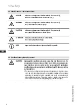
Page 4: ...tion or tips on simplifying work WARNING Inadequately qualified personnel poses the risk of accidents the consequence being serious or fatal injury Work on compressors must therefore only be performed by personnel with hereinafter qualifications and appropriate to additional qualification according to EN 60079 14 For example a refrigeration technician refrigeration mechatronic engi neer As well as...

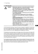
Page 5: ...lf We assume that the appli cable regulations standards and technical rules are followed in installation and during operation The plant constructor operator must evaluate the interactions with other devices and components of the system and with the environment especially regarding potential ignition sources WARNING Refrigerating compressors are pressurised machines and there fore require particula...

Page 6: ... well as observance of the operating limits and listed stand ards must be ensured in any case Likewise all accessories available from approved and specially marked by GEA are exclusively approved according to their intended use for attachment to and operation with GEA compressors of appliance category 2 in accordance with Directive 2014 34 EU 1 4 Intended use WARNING Any other use of the compresso...

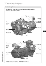
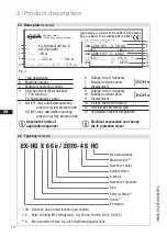
Page 7: ...or with oil pump lubrication For use in explosion endangered areas Fig 1 Fig 2 Oil sight glass Valve plate Cylinder cover Discharge shut off valve Oil pump Terminal box Potential equalization Suction shut off valve Drive section Motor section Dimension and connection values can be found in chapter 10 Transport eyelet Name plate ...

Page 8: ... highest heat potential are controlled with temperature sensors Ex b The installation of the electronic control unit INT69 EX2 and the safety barrier both included in the scope of supply is therefore absolutely necessary The connection areas for load circuits are designed according to the requirements of the appliance category in Ex e The circuits for the temperature sensors of the used ignition s...

Page 9: ...on the connecting areas of the coil are placed in a housing that complies with the requirements of the protection type increased safety Ex e The oil differential pressure sensor INT250 Ex from Kriwan is executed as a simple electrical operating device without a recognised ignition protection type To ensure reliable operation however it must be equipped as an intrinsically safe electrical circuit w...

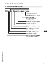
Page 10: ...g air conditioning applications Fig 3 HC for hydrocarbons Motor variant Number of poles Swept volume e series Number of cylinders Size Ester oil filling Series Ex design 1 Type designation 6 Voltage circuit frequency 2 Machine number 7 Nominal rotation speed 3 Maximum operating current 8 Displacement 4 Starting current Rotor blocked 9 Voltage circuit frequency Y Part winding 1 10 Nominal rotation ...

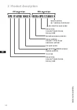
Page 11: ...s not underground buildings Suitability for gas explosive area Device category 2 zone 1 Temperature class T3 max 200 C Equipment protection level Explosion subgroups IIB Offshore paint finish IIC ESD paint finish Intrinsically safe equipment Increased safety Flameproof enclosure heater option Europ explosion protection acc to Direc 2014 34 EU Encapsulation magnetic coil option ...

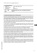
Page 12: ...tional explosion protection Year of test Test report number Year of test Bureau Veritas Consumer Products Services Germany GmbH Special conditions see Conditions of Certification Special conditions see point 17 of the EC type examination certificate Test report number ATmospheres EXplosibles european explosion protection ATEX approval type IECEx approval type ...

Page 13: ...y the manufacturer may only be performed by personnel who have been specially trained on combustible refrigerants If the compressor has to be removed from the system for inspection maintenance repair the remaining refrigerant must be suctioned out and the compressor evacuated filled with nitrogen 0 5 bar and closed gas tight The compressor must be equipped with a tag that clearly states that the c...

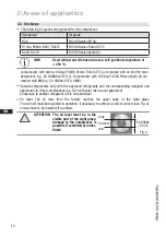
Page 14: ...f or added Operate compressors only with the approved refrigerants and the corresponding assigned and approved oils Other combinations e g R22 with ester oils are not permitted Conversion to another refrigerant oil is not permitted ATTENTION The oil level must be in the visible part of the sight glass damage to the compressor is possible if overfilled or under filled max min Oil level The followin...

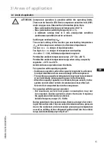
Page 15: ...y regulator 20 C to 50 C Avoid continuous operation near the limits For operation with capacity regulator Continuous operation when the capacity regulator is activated is not permissible and can cause damage to the compressor The suction gas superheat temperature may need to be reduced or set individually when operating near to the threshold When the capacity regulator is activated the gas velocit...

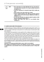
Page 16: ...e INT69 EX2 The permissible limit temperatures for normal operation of the compressor were set with 130 C for the motor and with 140 C for the hot gas side of the cylinder cover If one of those values is exceeded the compressor is shut down by the control device INT69 EX2 Besides the installation according to wiring diagram the operator installer does not have to regard other parameters for the co...

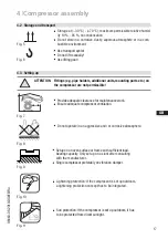
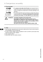
Page 17: ...corrosive atmosphere Fig 7 Fig 8 Fig 9 Fig 10 F E D C B 1 2 3 Lieferantenzeichnung Bearb Datum Änderungs Nr Werkstoff Ausgangsteil bzw Rohteil Gepr Zone 1 x Blatt Benennung Zeichn Nr Teile Nr x xxxx xxxxx x Maßstab 1 1 Sun protection If the compressor is set up outdoors it has to be protected from direct sunlight Fig 11 4 2 Storage and transport Use transport eyelet Do not lift manually Use liftin...

Page 18: ...nal diameter 4 4 Pipe connections ATTENTION An explosive atmosphere must not be present Do not solder as long as the compressor is under pressure Superheating can damage the valve Remove the pipe supports therefore from the valve for soldering and accordingly cool the valve body during and after soldering Only solder using inert gas to inhibit oxidation products scale Pipes and system components m...

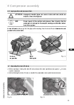
Page 19: ...e valve spindle seal clockwise Fig 14 Fig 15 4 6 Laying suction and pressure lines Fig 13 A rule of thumb Always lay the first pipe section starting from the shut off valve downwards and parallel to the drive shaft ATTENTION Improperly installed pipes can cause cracks and tears which can result in a loss of refrigerant INFO Proper layout of the suction and pressure lines directly after the compres...

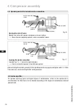
Page 20: ...right clockwise Service connection opened shut off valve opened Connection blocked Spindle Spindle Connection open Compressor Compressor Service connection closed Service connection opened After activating the spindle generally fit the spindle protection cap again and tighten with 14 16 Nm This serves as a second sealing feature during operation For systems with long pipes and higher degree of con...

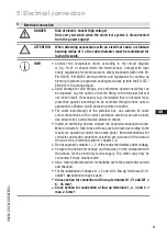
Page 21: ...ing can be achieved through check nuts or appropriate adhesive Avoid abrasion points on cables For cable lead through at the terminal box use suitable Ex cable screw connections in the correct protective version see name plate Use strain relief Avoid abrasion points on cables Install all switching devices outside the explosion endangered area Motor contactors feed lines and fuses are to be rated a...

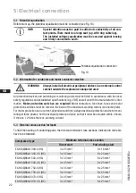
Page 22: ...ations and established specifications e g VDE as well as with the manufacturer s infor mation Motor protection switches are required Motor contactors feed lines fuses and motor protection switches must be rated on the basis of the maximum working current see name plate For motor protection use a current dependent and time delayed overload protection device for moni toring all three phases Set the ...

Page 23: ...s in reversed fields of rotation and can cause motor damage After the motor has started up with part winding 1 part winding 2 must be switched on after max 1 second delay Failure to comply can be detrimental to the service life of the motor ATTENTION Terminal boxes and cable screw connections must be properly closed in order to achieve the protective class IP66 Use Ex cable screw fittings pay atte...

Page 24: ...utside of the explosion endangered area Power section QA1 Main switch QA2 Performance contactor direct start FC1 1 Motor safety switch EC1 Compressor motor BT1 PTC sensor motor winding BT2 Thermal protection thermostat UC1 Terminal box compressor X KK Terminal strip in terminal box compressor X SS Terminal strip in external switch cabinet 5 5 Circuit diagrams for power section ATTENTION Ensure tha...

Page 25: ...QA1 L1 L2 L3 N PE FC1 1 I I I 1 2 QA2 1 L1 L1 L2 L2 L3 L3 U1 U2 V1 V2 W1 W2 2 3 4 3 4 5 6 5 6 M 3 Y YY PE PE 7 9 4 BT2 1 2 BT2 5 L1 L2 L3 N PE QA1 L1 L2 L3 N PE FC1 1 I I I 1 2 QA2 1 L1 L1 L2 L2 L3 L3 U1 U2 V1 V2 W1 W2 2 3 4 3 4 5 6 5 6 M 3 Y YY PE PE FC1 2 I I I 1 2 QA3 3 4 7 5 6 9 4 BT2 1 2 BT2 5 L1 L2 L3 N PE BT2 BT2 PA PA XKK D 1 1 b 4 XKK D 2 1 b 4 XKK D 3 1 b 4 XKK D 4 1 b 4 XKK PW 1 1 b 9 X...

Page 26: ... in the external switch cabinet X KK Terminal strip in the supplemental terminal box with recognised protection type Optional KF1 Time delay relay on delay max 90 sec bypass time at start KF2 Time delay relay drop off delay max 90 sec function begins when the oil pressure monitoring is reached during operation BP5 Oil differential pressure sensor Kriwan EB1 Oil sump heater ATEX design FA2 Switchin...

Page 27: ...L2 L3 N PE FC2 1 SF1 FC1 1 XSS 1 1 3 2 4 PA A1 A2 KF3 P öl Kriwan 1 3 or 2 4 br rot 13 14 QA2 PE PE 8 BT3 A2 A1 KF1 Max 90sec 16 15 KF2 18 16 15 KF1 A1 A2 QA2 18 PE PE PE FC2 2 23 24 QA2 9 8 EB1 10 10 19 20 11 LR P 12 L1 L2 L3 N PE PE PE 12 11 KF3 14 PE 12 11 14 BP2 P PE PE PE 2 4 5 3 6 1 2 3 4 FB1 Δ I 7 1 2 11 12 14 L N XKK 3 6 7 9 24V A1 A2 X1 KF2 12 11 14 BP1 P XKK D 1 XKK D 2 XKK D 3 XKK D 4 T...

Page 28: ...binet X KK Terminal strip in the supplemental terminal box with recognised protection type Optional KF1 Time delay relay on delay max 90 sec bypass time at start KF2 Time delay relay drop off delay max 90 sec function begins when the oil pressure monitoring is reached during operation BP5 Oil differential pressure sensor Kriwan EB1 Oil sump heater ATEX design FA2 Switching repeater oil pressure co...

Page 29: ...FC1 1 FC1 2 11 KF3 14 1 3 2 4 PA A1 A2 KF3 1 10 Y1 Y2 KF2 max 90s 2 11 33 34 QA2 A2 A1 KF1 max 90s 16 15 KF2 18 16 15 KF1 A1 A2 QA2 18 13 14 KF5 43 44 QA2 A1 A2 QA3 A2 A1 KF5 max 1s L1 L2 L3 N PE XSS 1 P öl Kriwan or br rot PE PE 8 BT3 PE PE PE 9 8 EB1 10 10 11 LR 12 PE PE PE 12 11 14 12 11 14 BP2 P PE PE PE 2 4 5 3 6 7 FC2 2 23 24 QA2 19 20 P 1 2 3 4 FB1 Δ I 11 12 14 L N 1 2 XKK 3 6 7 9 24V BP1 P...

Page 30: ...3 SELV or PELV safety transformer must be installed in series The safety transformer must conform to EN 62368 1 5 8 Electronic trigger unit INT69 EX2 ATTENTION Install INT69 EX2 outside the explosion endangered area The INT69 EX2 trigger unit must be installed according to the wiring diagram INFO The relay switching output is executed as a floating changeover contact This electrical circuit operat...

Page 31: ...and temperature monitoring of the system according to the wiring diagram fig 20 21 Pay attention to the PTC sensor connection Terminals 1 2 on the trigger unit INT69 EX2 and terminals PTC 1 and PTC 2 on the compressor terminal board must not come into contact with mains voltage This would destroy the trigger unit and PTC sensors The supply voltage at L1 N for DC 24 V version must be identical to t...

Page 32: ... 30 V Uo Ui2 15 8 30 V Io Ii1 200 300 mA Io Ii2 200 300 mA Po Pi1 395 9000 mW Po Pi2 395 9000 mW Lo Li1 Li2 Lc 0 5 0 25 mH Co Ci1 Ci2 Cc 478 50 nF To verify the intrinsic safety of the hot gas sensor the following values must be rated Values for Lc Cc represent example values for the total output length of 250 m and they must be updated by the system builder in accordance with your design Li1 Li2 ...

Page 33: ... a corresponding safety standard without the inclusion of the compressor 6 3 Leak test Carry out the leak test on the refrigerating plant in accordance with EN 378 2 or a corresponding safety standard while always observing the maximum permissible overpressure for the compressor DANGER Risk of bursting The compressor must only be pressurised using nitrogen N2 Never pressurise with oxygen or other ...

Page 34: ...topped up in vapour form on the suction side or taking suitable precautions also in liquid form at the inlet to the evaporator 6 5 Refrigerant charge ATTENTION Do not start the compressor if it is under vacuum Do not apply any voltage even for test purposes must only be operated with refrigerant Under vacuum the spark over and creepage current distances of the terminal board connection bolts short...

Page 35: ...sible in the sight glass To prevent slugging The complete refrigeration plant must be properly designed All components must be compatibly rated with each other with regard to output particularly the evaporator and expansion valves Suction gas superheating at the compressor input should be min 7 10 K check the setting of the expansion valve The system must reach a state of equilibrium Particularly ...

Page 36: ...ssor regularly with a damp cloth Oil change Not mandatory in factory produced series systems In field installations or when operating near the application limit for the first time after 100 to 200 operating hours then approx every 3 years or 10 000 12 000 operating hours Dispose of old oil according to the regulations observe national regulations WARNING All work must be performed only by qualifie...

Page 37: ...y be carried out at the factory The following torques must be used when re assembling the compressor INFO If system function must be guaranteed with certainty we recom mend a standby compressor INFO Cylinder head valve plate starting from the middle tighten screws crosswise in at least two steps torque 50 100 EX HG66e 1340 4 S 1540 4 S 1750 4 S 2070 4 S Designation Item No Item No Item No Item No ...

Page 38: ...itch off must be greater than or equal to the maximum assumable short circuit current at the installation location The EC type examination certifications must be observed ATTENTION Valve magnets are only operational if they are mounted on the valve belonging to them INFO Using the Norgren magnetic coil ID no 4280 4281 GEA part no 70123 70124 70125 70149 effectively reduces the permissible ambient ...

Page 39: ...ion device RCD must be used with a rated triggering current not exceeding 100 mA Residual current protective equipment with a rated triggering current of 30 mA is preferable The maximum switch off time of the equipment for must not exceed 5 seconds for rated triggering current and 0 15 seconds in case of five times the rated triggering current In an IT system an insulation monitoring device must b...

Page 40: ...ly protected During assembly and installation of the oil differential pressure sensor INT250 Ex the requirements of EN 60079 14 and the BetrSichV operational safety regulations must be met In addition nationally valid laws regulations in Germany VDE 0100 or provisions must be observed Additional installation instructions and installation deinstallation instructions can be obtained from the accompa...

Page 41: ...62 37 2 170 275 309 EX HG66e 1540 4 S 133 8 160 5 75 44 4 196 335 314 EX HG66e 1750 4 152 2 182 6 72 42 4 196 335 308 EX HG66e 1750 4 S 152 2 182 6 87 50 7 222 361 309 EX HG66e 2070 4 180 0 216 0 85 50 7 196 335 305 64 2 5 8 EX HG66e 2070 4 S 180 0 216 0 103 60 7 222 361 306 9 Technical data 1 2 3 2 4 Tolerance 10 relative to the mean value of the voltage range The specifications for max power con...

Page 42: ...lator Dreilochanschluss für TRAXOIL 3xM6x10 Three hole connection for TRAXOIL 3xM6x10 Dreilochanschluss für ESK AC R CARLY 3xM6x10 Three hole connection for ESK AC R CARLY 3xM6x10 381 535 305 Schwingungsdämpfer Vibration absorbers 30 M12 50 25 W 2x W 2x PA M32x1 5 2x Y 810 2 404 Y A1 SV 4 5 6 2 3 4 5 6 Zeichn Nr Drawing no 3 2 Part No Maßstab bis up to über above Freigabe Appr z y x w u t s DIN IS...

Page 43: ...ion oil return from oil separator 1 4 NPTF F Oil drain M12 x 1 5 H Oil charge plug 1 4 NPTF J Connection oil sump heater M22 x 1 5 K Sight glass 3 x M6 L1 Thermal protection thermostat 1 8 NPTF M Oil strainer M12 x 1 5 O Connection oil level regulator 3 x M6 ÖV Connection oil service valve 1 4 NPTF PA Potential equalisation connection M8 W Connection refrigerant injection 2 x 1 8 NPTF Operate thes...

Page 44: ......

Page 45: ......

Page 46: ......

Page 47: ......

Page 48: ......

Page 49: ......

Page 50: ......

Page 51: ...any questions about installation operation and accessories please contact our technical service or specialist wholesaler and or our representative The GEA service team can be contacted by phone with a toll free hotline 00 800 800 000 88 or via e mail info gea com Yours faithfully GEA Bock GmbH Benzstraße 7 72636 Frickenhausen Germany Service ...

Page 52: ...one 49 0 7022 9454 0 Fax 49 0 7022 9454 137 info gea com gea com GEA Group is a global engineering company with multi billion euro sales and operations in more than 50 countries Founded in 1881 the company is one of the largest providers of innovative equipment and process technology GEA Group is listed in the STOXX Europe 600 index ...

Reviews: