2
D
GB
F
E
96031-11.2011-DGbFEI
1
Safety
4
1.1 Identification of safety instructions
1.2 Qualifications required of personnel
1.3 General safety instructions
1.4 Intended use
2
Product description
6
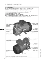
2.1 Short description
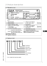
2.2 Name plate
2.3 Type key
3
Areas of application
8
3.1 Refrigerants
3.2 Oil charge
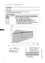
3.3 Limits of application
4
Compressor assembly
9
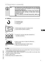
4.1 Setting up
4.2 Pipes
4.3 Flange shut-off valves (HP/LP)
4.4 Operating mode of the lockable service connections
4.5 Operating the shut-off valves
4.6 Pipe connections
4.7 Laying suction and pressure lines
5
Electrical connection
12
5.1 Information for contactor and motor contactor selection
5.2 Standad motor, designed for direct or part winding start
5.3 Maine line wiring diagram for part winding
5.4 Electronic trigger unit MP 10
5.5 Connection of the electronic trigger unit MP 10
5.6 Functional test of the electronic trigger unit MP 10
5.7 Oil sump heater
5.8 Fan motor
6
Commissioning
18
6.1 Preparations for start-up
6.2 Pressure strength test
6.3 Leak test
6.4 Evacuation
6.5 Refrigerant charge
6.6 Start-up
6.7 Decompression valves
6.8 Avoiding slugging
7
Maintenance
22
7.1 Preparation
7.2 Work to be carried out
7.3 Spare parts recommendation
7.4 Accessories
7.5 Decommissioning
8
Technical data
24
9
Dimensions and connections
25
10 Declaration of conformity and installation
26
11 Service
27
About these instructions
Read these instructions before assembly and before using the compressor. This will avoid misunder
-
standings
and prevent damage. Improper assembly and use of the compressor can result in serious
or fatal injury.
Observe the safety instructions contained in these instructions.
These instructions must be passed onto the end customer along with the unit in which the compres
-
sor is installed.
GEA Bock GmbH
72636 Frickenhausen
GEA Bock GmbH
Benzstraße 7
72636 Frickenhausen
Germany
Tel49 7022 9454 0
Fax
+49 7022 9454 137
mail@bock.de
www.bock.de
Manufacturer
Contact


