background image

Summary of Contents for Bock EX-HG88e Series

Page 1: ...HG88e 3235 4 3G HC EX HG88e 2400 4 S 3G EX HGX88e 2400 4 S 3G EX HG88e 2400 4 S 3G HC EX HG88e 2735 4 S 3G EX HGX88e 2735 4 S 3G EX HG88e 2735 4 S 3G HC EX HG88e 3235 4 S 3G EX HGX88e 3235 4 S 3G EX HG88e 3235 4 S 3G HC GEA Bock EX HG88e Assembly instructions 96403 08 2019 Gb Translation of the original instructions Device category 3 G acc to directive 2014 34 EU ...

Page 2: ...arbons 3 3 Oil charge 3 4 Limits of application About these instructions Read these instructions before assembly and before using the compressor This will avoid misunder standings and prevent damage Improper assembly and use of the compressor can result in serious or fatal injury Observe the safety instructions contained in these instructions These instructions must be passed onto the end customer...

Page 3: ...ger unit INT69 G Ex 5 8 Connection of the electronic trigger INT69 G Ex 5 9 Functional test of the electronic trigger unit INT69 G Ex 6 Commissioning 32 6 1 Preparations for start up 6 2 Pressure strength test 6 3 Leak test 6 4 Evacuation 6 5 Refrigerant charge 6 6 Start up 6 7 Avoiding liquid sluggings 6 8 Preventing icing on the compressor 7 Maintenance 35 7 1 Preparation 7 2 Work to be carried ...

Page 4: ...tion or tips on simplifying work WARNING Inadequately qualified personnel poses the risk of accidents the consequence being serious or fatal injury Work on compressors must therefore only be performed by personnel with hereinafter qualifications and appropriate to additional qualification according to EN 60079 14 For example a refrigeration technician refrigeration mechatronic engi neer As well as...

Page 5: ...pli cable regulations standards and technical rules are followed in installation and during operation The plant constructor operator must evaluate the interactions with other devices and components of the system and with the environment especially regarding potential ignition sources 1 3 Safety instructions WARNING Refrigerating compressors are pressurised machines and there fore require particula...

Page 6: ...s well as observance of the operating limits and listed standards must be ensured in any case Likewise all accessories available from approved and specially marked by GEA are exclusively approved according to their intended use for attachment to and operation with GEA compressors of appliance category 2 in accordance with Directive 2014 34 EU 1 4 Intended use WARNING Any other use of the compresso...

Page 7: ...eciprocating compressor with suction gas cooled drive motor The stream of refrigerant sucked out of the evaporator flows over the motor and cools it intensively In this way the motor can be kept at a relatively low temperature level particularly under high loads Motor section Valve plate Transport eyelet Discharge shut off valve Oil pump Suction shut off valve Name plate Oil sight glass Cylinder c...

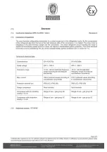
Page 8: ... To prevent ignition risk caused by working materials also during system malfunctions all used working materials have to meet the requirements for the temperature class of the compressor The surface temperature of the compressor may not exceed 80 of the ignition temperature of the working material For this reason all working materials need to have an auto ignition temperature of 250 C The scope of...

Page 9: ...erified that the heating elements prevent the exceeding of the temperature class of the compressor The control has to be carried out in a way that the heating element can only be operated during shutdown of the compressor The magnetic coil of the capacity regulator is designed in the protection type encapsulation Ex m to protect against explosion risks In addition the connecting areas of the coil ...

Page 10: ...r variant 4 Number of poles Swept volume e series 3 Number of cylinders Size Ester oil filling 2 Series 1 Ex design Fig 2 1 2 4 3 5 6 7 8 9 10 11 13 14 12 15 2 3 Name plate example Observe the limits of application diagrams 1 Type designation 2 Machine number 3 Type code 4 Maximum operating current 5 Starting current rotor blocked Y Part winding 1 YY Part winding 1 and 2 6 ND LP max admissible ove...

Page 11: ...nderground buildings Suitability for gas explosive area Device category 3 zone 2 Sealed equipment option Temperature class T3 max 200 C Equipment protection level Explosion subgroups IIB Offshore paint finish IIC ESD paint finish Europ explosion protection acc to Direc 2014 34 EU Non sparking equipment Increased safety Flameproof enclosure heater option Encapsulation magnetic coil option ...

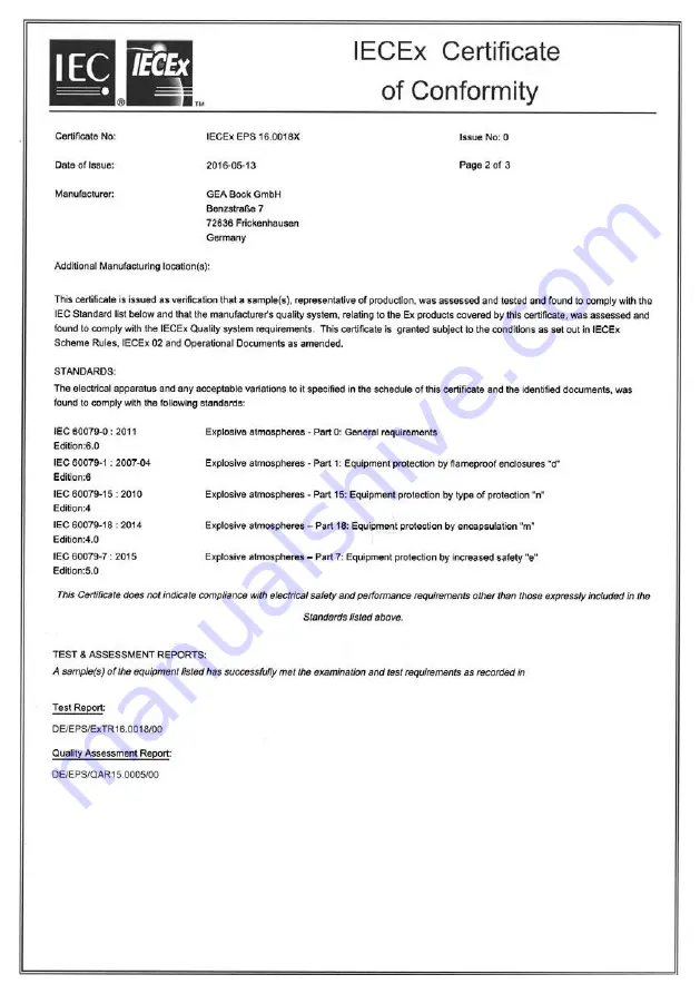
Page 12: ...sion protection Year of test Test report number Year of test Bureau Veritas Consumer Products Services Germany GmbH ATEX Certificate of Conformity IECEx Certificate of Conformity Special conditions see Conditions of Certification Special conditions see point 17 of the EC type examination certificate Test report number ATmospheres EXplosibles european explosion protection ...

Page 13: ...ially trained on combustible refrigerants If the compressor has to be removed from the system for inspection maintenance repair the remaining refrigerant must be suctioned out and the compressor evacuated filled with nitrogen 0 5 bar and closed gas tight The compressor must be equipped with a tag that clearly states that the compressor was operated with combustible refrigerant name the refrigerant...

Page 14: ...emperature of 250 C Compressors with ester oil filling FUCHS Reniso Triton SE 55 are marked with an X in the type designation e g EX HGX88e 3235 4 3G Compressors with oil filling FUCHS Reniso Snyth 68 are marked with HC e g EX HG88e 3235 4 3G HC Oil level The oil level from the factory reaches the upper edge of the sight glass The oil level must be regulated in operation if necessary to achieve a ...

Page 15: ...y regulator 20 C bis 50 C Avoid continuous operation near the limits For operation with capacity regulator Continuous operation when the capacity regulator is activated is not permissible and can cause damage to the compressor The suction gas superheat temperature may need to be reduced or set individually when operating near to the threshold When the capacity regulator is activated the gas veloci...

Page 16: ... factory filled with inert gas Leave this service charge in the compressor for as long as possible and prevent the ingress of air Check the compressor for transport damage before starting any work Before starting work obtain written work release Observenationalregulationswhensettingupexplosion protected systems within the EU ATEX Directive 1999 92 EG EN 60079 14 EN 60079 17 a o Use only tools perm...

Page 17: ...nbehandlung Härte Blatt 00 Benennung 8 00 Zeichn Nr Teile Nr Oberflächenangaben ISO 1302 x xxxx xxxxx x Maßstab 1 1 Wasserwaage für Indesign Der Lieferant muß sicherstellen dass die Ware in einwandfreiem Zustand angeliefert wird Korrosions schutz Verpackung für sicheren Transport Rz 25 Rz 160 s 25 z y x w u t 0 05 Rz 1 6 0 3 0 7 1 6 2 Rz 16 6 3 Rz 63 Rz 6 3 Rz 12 5 Fig 10 Fig 11 Installation of pi...

Page 18: ...g 13 The compressor is now short circuited and delivers from the outflow directly into the intake The pressure differential consequently decreases substantially As a result the torque on the drive shaft of the compressor is considerably diminished The drive motor can now start with a low level of starting torque As soon as the motor and the compressor reach their rated speed the solenoid valve clo...

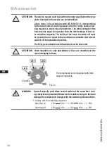
Page 19: ...overloading Connect the heat protection thermostat in series on the safety chain of the control circuit to switch off the compressor if necessary Follow these instructions to avoid thermal overloading Fig 14 Solenoid valve dead Non return valve open A rule of thumb Always lay the first pipe section starting from the shut off valve downwards and parallel to the drive shaft ATTENTION Improperly inst...

Page 20: ...se as far as it will go Shut off valve completely opened service connection closed Fig 19 Opening the service connection Spindle Turn 1 2 1 turn clockwise Service connection opened shut off valve opened Connection blocked Spindle Spindle Connection open Compressor Compressor Service connection closed Service connection opened After activating the spindle generally fit the spindle protection cap ag...

Page 21: ...rain relief Avoid abrasion points on cables Install all switching devices outside the explosion endangered area Motor contactors feed lines and fuses are to be rated according to the maximum operating current see name plate Recommendations for contactor and motor protection selection are included in the table at the end of the Electrical system chapter 5 1 Do not separate contacts 1 2 of the motor...

Page 22: ...ss sections indicated in the table have to be followed INFO Theinsulationplateusedontheterminalboardservestoguarantee the air and creepage paths It is therefore essential that it remains on the terminal board Use tubular cable lugs for the electrical connection to the terminal board All protection devices and switching or monitoring units must be fitted in accordance with the local safety regulati...

Page 23: ...rt PW Anlauf ist die Verwendung einer mechanischen ufentlastung mit Bypass Magnetventil nicht erforderlich edarfsfall kann der Anlaufstrom beim PW Anlauf zusätzlich um bis zu 10 durch endung einer mechanischen Anlaufentlastung Zubehör verringert werden t der Motor für Direktstart geschaltet ilwicklungsstart sind die Brücken n und die Motorzuleitung gemäß a anzuschließen NUNG Nichtbeachten führt zu...

Page 24: ...on endangered area Power section QA1 Main switch QA2 Motor contactor FC1 1 Motor safety switch EC1 Compressor motor BT1 PTC sensor motor winding BT2 Thermal protection thermostat UC1 Terminal box compressor X KK Terminal strip in terminal box compressor X SS Terminal strip in external switch cabinet 5 4 Circuit diagrams for power section ATTENTION Ensure that power is supplied via QA2 to winding 1...

Page 25: ...t Winding XKK BT1 UC1 XSS Netz 400V 50Hz XKK BT1 UC1 QA1 L1 L2 L3 N PE FC1 1 I I I 1 2 QA2 1 2 3 4 3 4 5 6 5 6 PE PE XKK 1 2 L1 L2 L3 N PE QA1 L1 L2 L3 N PE FC1 1 I I I 1 2 QA2 1 3 4 3 5 6 5 PE PE FC1 2 I I I 1 2 QA3 3 4 XKK 1 5 6 2 3 BT2 4 L1 L2 L3 N PE BT2 BT2 BT2 5 6 3 BT2 4 BT2 BT2 BT2 5 6 EC1 3 M Θ EC1 3 M Θ 2 4 6 7 7 XKK D 1 2 1 3 XKK D 2 2 1 3 XKK PW 1 3 1 3 XKK PW 2 3 1 3 P o w e r s e c t...

Page 26: ...witch cabinet X KK Terminal strip in the supplemental terminal box with recognised protection type Optional KF1 Time delay relay on delay max 90 sec bypass time at start KF2 Time delay relay drop off delay max 90 sec on begins when the oil pressure monitoring is reached during operation BP3 Oil differential pressure sensor INT250 Ex Kriwan EB1 Oil sump heater ATEX design LR Capacity regulator ATEX...

Page 27: ...chten KF4 INT69G BP3 max 90sec max 90sec Externe Freigabe LR L1 L2 L3 N PE FC2 1 SF1 FC1 1 XSS 1 2 3 4 PE PE 5 6 7 BP2 P PE PE A1 A2 KF3 P öl Kriwan or br rot Y1 Y2 KF2 13 14 QA2 PE PE 11 BT3 A2 A1 KF1 16 15 KF2 18 16 15 KF1 A1 A2 QA2 18 PE XKK 8 FC2 2 23 24 QA2 12 9 13 10 18 19 14 LR P 15 L1 L2 L3 N PE PE PE XKK PE 11 12 1 2 3 4 FB1 Δ I 1 2 PE EB1 L N 11 12 14 OG OG BP1 P XKK D 1 XKK D 2 INT69 EX...

Page 28: ...upplemental terminal box with recognised protection type Optional KF1 Time delay relay on delay max 90 sec bypass time at start KF2 Time delay relay drop off delay max 90 sec function begins when the oil pressure monitoring is reached during operation BP3 Oil differential pressure sensor INT250 Kriwan EB1 Oil sump heater ATEX design LR Capacity regulator ATEX design Operate these components with t...

Page 29: ...KF4 INT69G L1 L2 L3 N PE 12 FC2 1 SF1 FC1 1 FC1 2 11 KF3 14 XSS 1 2 3 4 PE PE 5 6 7 BP2 P PE PE A1 A2 KF3 P öl Kriwan or Y1 Y2 KF2 br 33 34 QA2 rot A2 A1 KF1 PE PE 11 BT3 16 15 KF2 18 16 15 KF1 A1 A2 QA2 18 13 14 KF5 43 44 QA2 A1 A2 QA3 12 A2 A1 KF5 PE FC2 2 23 24 QA2 13 18 19 14 LR P 15 L1 L2 L3 N PE PE PE 1 2 PE EB1 XKK 8 9 10 XKK PE 11 12 1 2 3 4 FB1 Δ I L N 12 14 11 OG OG BP1 P XKK PW 1 XKK PW...

Page 30: ... 3 SELV or PELV safety transformer must be installed in series The safety transformer must conform to EN 60950 1 5 8 Electronic trigger unit INT69 EX2 ATTENTION Install INT69 EX2 outside the explosion endangered area The INT69 EX2 trigger unit must be installed according to the wiring diagram INFO The relay switching output is executed as a floating changeover contact This electrical circuit opera...

Page 31: ...r circuits and clearly marked in accordance with EN 60079 14 Appropriate measures e g barrier must be taken Make the connecting lines intrinsically safe Do not exceed the maximum resistance of 50 Ω Take into account the resistance values of the thermal protection thermostats Motor sensor as triple PTC resistor 50 450 Ω Rcold at 25 C not intrinsically safe Hot gas sensor Cold resistance 100 Ω Rcold...

Page 32: ...ted in the factory for pressure integrity If however the entire system is to be subjected to a pressure integrity test this should be carried out in accordance with EN 378 2 or a corresponding safety standard without the inclusion of the compressor 6 3 Leak test Carry out the leak test on the refrigerating plant in accordance with EN 378 2 or a corresponding safety standard while always observing ...

Page 33: ...topped up in vapour form on the suction side or taking suitable precautions also in liquid form at the inlet to the evaporator 6 5 Refrigerant charge ATTENTION Do not start the compressor if it is under vacuum Do not apply any voltage even for test purposes must only be operated with refrigerant Under vacuum the spark over and creepage current distances of the terminal board connection bolts short...

Page 34: ...isible in the sight glass To prevent slugging The complete refrigeration plant must be properly designed All components must be compatibly rated with each other with regard to output particularly the evaporator and expansion valves Suction gas superheating at the compressor input should be min 7 10 K check the setting of the expansion valve The system must reach a state of equilibrium Particularly...

Page 35: ...ssor regularly with a damp cloth Oil change Not mandatory in factory produced series systems In field installations or when operating near the application limit for the first time after 100 to 200 operating hours then approx every 3 years or 10 000 12 000 operating hours Dispose of old oil according to the regulations observe national regulations WARNING All work must be performed only by qualifie...

Page 36: ...07 81870 HC Set of valve plate 81617 81621 81622 Set of oil pump 80116 7 4 Screw connections 7 3 Spare part recommendation The following torques must be used when re assembling the compressor Cylinder cover bearing cover M10 75 Nm Oil filler plug oil drain plug oil sump heater M22x1 5 100 Nm Flange connection soldering supports for shut off valves 7 16 M10 M12 13 Nm 60 Nm 90 Nm Plug 1 8 NPTF 25 Nm...

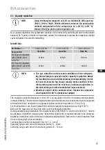
Page 37: ... 12 mm 8 1 Capacity regulation By a capacity regulation the compressor capacity can be reduced by switching off up to three cylinder banks by 25 each in relation to maximum power It is necessary to replace the respective cylinder cover included in the kit for retrofitting Retrofit kits INFO The gas velocities and pressure conditions of the refrigerat ing plant change in operation with capacity reg...

Page 38: ...only within the data specified on the type plate Changes to the device are not permitted A fuse max 3 x lB accordance with IEC 6 0127 2 1 corresponding to the rated current must be placed in front of every valve actua ting magnet as short circuit protection The rated voltage of the fuse must be equal to or greater than the rated voltage of the val ve actuation magnets The ability of the fuses to s...

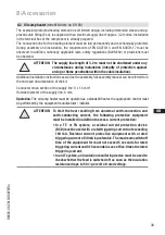
Page 39: ...ter must be operated as a standstill heater the appropriate control must be performed by the equipment manufacturer installer 8 Accessories ATTENTION To limit the heat resulting from abnormal earth connection and earth conducting current the following protective equipment must be installed in addition to excess current protection In a TT or TN system a residual current protection device RCD must b...

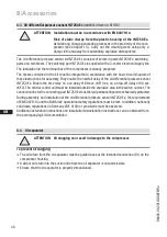
Page 40: ...tected During assembly and installation of the oil differential pressure sensor INT250 Ex the requirements of EN 60079 14 and the BetrSichV operational safety regulations must be met In addition nationally valid laws regulations in Germany VDE 0100 or provisions must be observed Additional installation instructions and installation deinstallation instructions can be obtained from the accompanying ...

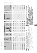
Page 41: ...88e 3235 4 3G 281 3 337 6 135 79 2 447 657 460 82 5 81 81 EX HG88e 3235 4 S 3G 281 3 337 6 162 93 9 538 791 469 83 82 82 1 2 3 2 4 5 9 Technical data Tolerance 10 relative to the mean value of the voltage range Other voltages and types of current on request The specifications for max power consumption apply for 50 Hz operation For 60 Hz operation the specifications have to be multiplied by the fac...

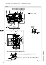
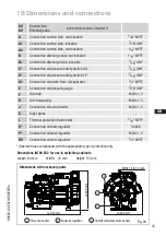
Page 42: ...735 4 3G 17296 EX HG88e 2735 4 3G HC 17300 Anschlüsse Connections SV Saugabsperrventil Rohr L mm Zoll 76 3 1 8 Suction line valve tube L mm inch DV Druckabsperrventil Rohr L mm Zoll 54 2 1 8 Discharge line valve tube L mm inch A Anschluss Saugseite nicht absperrbar Zoll inch 1 8 NPTF Connection suction side not lockable A1 Anschluss Saugseite absperrbar Zoll inch 7 16 UNF Connection suction side l...

Page 43: ...l separator 1 4 NPTF E Connection oil pressure gauge 7 16 UNF F Oil drain M22x1 5 H Oil charge plug M22x1 5 J Connection oil sump heater M22x1 5 K Sight glass L Thermal protection thermostat 1 8 NPTF O Connection oil level regulator 3 x M6 P Connection oil level regulator M20x1 5 ÖV Connection oil level regulator 1 4 NPTF Operate these components with the appropriate type of protection only 10 Dim...

Page 44: ......

Page 45: ......

Page 46: ......

Page 47: ......

Page 48: ......

Page 49: ......

Page 50: ...any questions about installation operation and accessories please contact our technical service or specialist wholesaler and or our representative The GEA service team can be contacted by phone with a toll free hotline 00 800 800 000 88 or via e mail info gea com Yours faithfully GEA Bock GmbH Benzstraße 7 72636 Frickenhausen Germany Service ...

Page 51: ...D GB F E I 51 96403 08 2019 DGbFEIRu ...

Page 52: ...one 49 0 7022 9454 0 Fax 49 0 7022 9454 137 info gea com gea com GEA Group is a global engineering company with multi billion euro sales and operations in more than 50 countries Founded in 1881 the company is one of the largest providers of innovative equipment and process technology GEA Group is listed in the STOXX Europe 600 index ...

Reviews: