D
GB
F
E
23
96460-12.2020-DGb
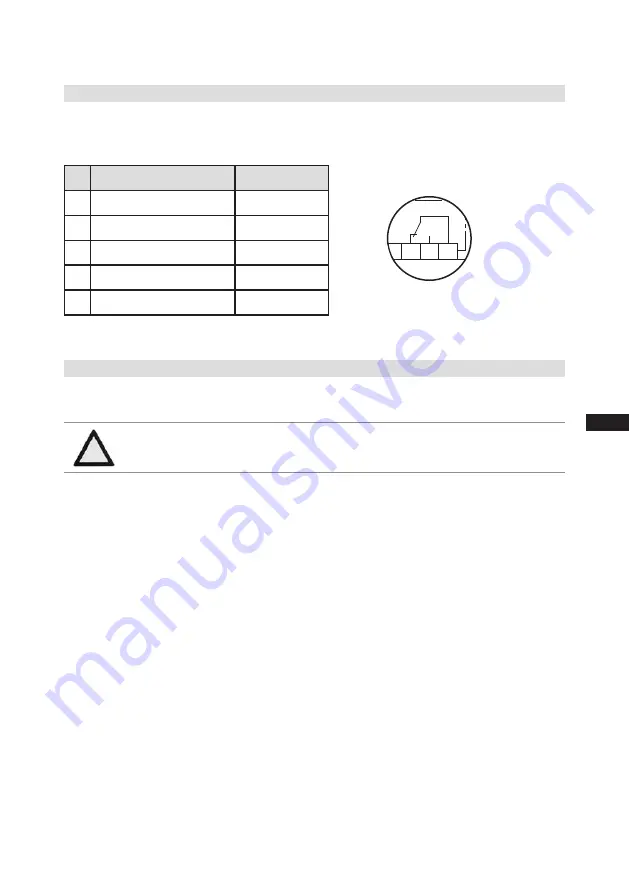
5.8 Function test of the trigger unit INT69 G
Before commissioning, after troubleshooting or making changes to the control power circuit, check
the functionality of the trigger unit. Perform this check using a continuity tester or gauge.
Trigger unit state
Relay position
1.
Deactivated state
11-12
2.
INT69 G switch-on
11-14
3.
Remove PTC connector
11-12
4.
Insert PTC connector
11-12
5.
Reset after mains on
11-14
Relay position INT69 G
B2 12 14 11
Fig. 17
5.9 Oil sump heater
In order to avoid damage to the compressor, the compressor is equipped with an oil sump heater as
a standard feature.
Operation:
The oil sump heater operates when the compressor is at a standstill.
When the compressor starts up, the oil sump heating switches off.
Connection:
The oil sump heater must be connected via an auxiliary contact (or parallel wired auxiliary
contact) of the compressor contactor to a separate electric circuit.
Electrical data: 230 V - 1 - 50/60 Hz, 160 W.
ATTENTION The oil sump heater must generally be connected and operated!
5
|
Electrical connection


