48
09665
-0
8.
20
18-
Gb
9
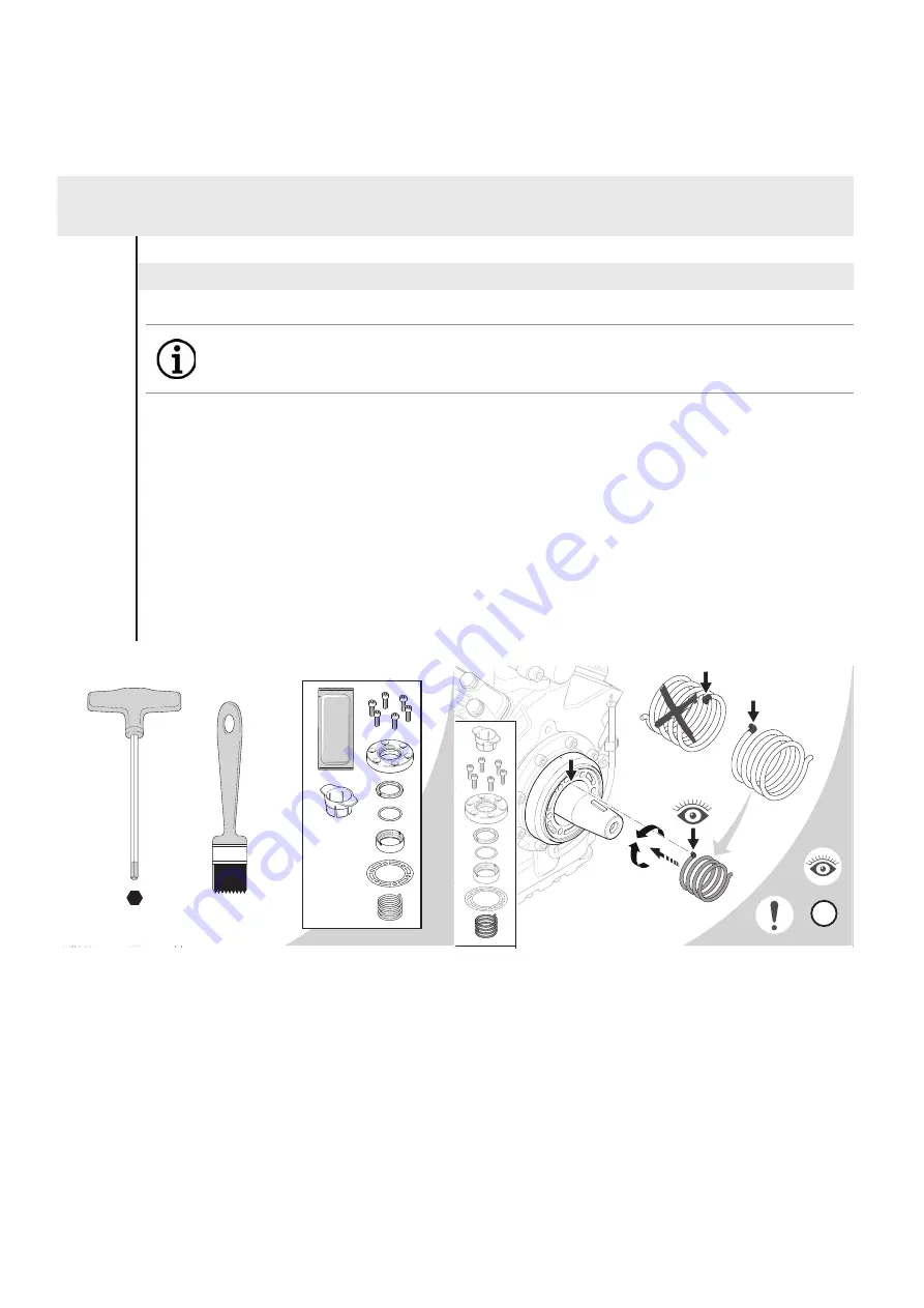
Fitting the shaft seal
Position in
parts list
Parts list position: 2010
Tools: Allen key 6 mm, brush
Working course
880
750
2050
2110
- Push the compression spring onto the crankshaft. Rotate the spring until the driving catch is engaged in the
crankshaft.
- Lubricate O-ring seating area in guide ring and O-ring with silicone grease.
- Push the guide ring with O-ring and sliding ring onto the crankshaft. Chamfer on sliding ring points outward.
Rotate all parts until the spring is engaged in the guide ring. Avoid scratches on the sliding ring!
- Apply silicone grease to rotary shaft seal in shaft seal cover.
- Install the shaft seal cover with the gasket using the protective sleeve. The inscription „TOP“ must be at the top.
- Press the shaft seal cover onto the bearing flange and tighten the screws.
- Turn the crankshaft by hand. Remove the protective sleeve.
- Install the leak oil collection device (only up to type code 014 and see also under service-kits:
clamping ring with oil felt).
12 I Assembly of compressor
INFO
Caution! Avoid damages! Pay attention to the markings!
Be sure to observe the detailed working steps illustrated below!
Observe tightening torques!
GEA Bock GmbH
Benzstraße 7, 72636 Frickenhausen, Germany
Phone: +49 7022 9454-0, Fax: +49 7022 9454-137
info@gea.com, www.gea.com
96445-01.2017-Gb
6 mm
POE
TOP
FK
TOP
TOP
1
2
3
4
5
6 mm
TOP
GEA Bock GmbH
Benzstraße 7, 72636 Frickenhausen, Germany
Phone: +49 7022 9454-0, Fax: +49 7022 9454-137
info@gea.com, www.gea.com
96445-01.2017-Gb
6 mm
POE
TOP
FK
TOP
TOP
1
2
3
4
5
6 mm
TOP
1


