The lubricating oil pressure safety switch protects the
compressor against too low lubricating oil pressure.
The lubricating oil pressure is the difference between
oil pressure and crankase pressure (=suction pressure)
indicated by pressure gauges. The lubricating oil
pressure safety switch reacts to this difference, which
should be at least 1 bar to ensure proper lubrication.
Two types of lubricating oil pressure safety
switches may be used:
a) with locking device and built-in thermal time
delay relay
(Danfoss differential pressure control
type MP 55A for NH3).
With this switch, a differential pressure between 0.3
- 4.5 bar can be adjusted by means of a set disc
under the upper pressure bellows inside the switch.
The
setting value should be at least 1 bar. If the
differential pressure decreases, the control current
circuit of the motor wil be interrupted with a delay
of 60 secs. A pilot lamp or klaxon can be connected
via an
auxiliary contact. When in “break” position, the
switch is locked. This lock should be released only
after 3 mins. by pressing the reset button on the
switch. The permanently set contact differential
amounts to 0.2 bar, so that the lubricating oil
pressure must be at least 1.2 bar to operate the
switch again. In order yet to re-start the compressor
and to allow it to build up a sufficient lubricating oil
pressure, a thermal time delay relay is provided,
which leaves the contacts closed during 60 seconds.
In order to check the safety switch for proper
operation, a test device is provided inside at the left
side of the switch. When this device is depressed
and kept in this position, the compressor should
stop after 60 seconds.
b) without locking device and without thermal
time delay relay
(Danfoss differential pressure
control type RC 260A).
With this safety switch, the lubricating oil pressure
can be adjusted between 0.5 and 4 bar by means
of a set disc which is accessible after removing the
front cover. The setting value should here, too, be
at least 1 bar. An auxiliary contact is provided for
connecting a pilot lamp or a klaxon. The
permanently set contact differential is 0.3 bar, so
that the lubricating oil pressure should be at least
1.3 bar to cause the switch to make circuit again.
In order to start the compressor and to allow it to
build up lubricating oil pressure, the contact of the
safety switch must have been shunted with the aid
of a separate time delay relay with locking device
or by a push button switch in the control
current circuit for the drive motor.
5.3 CRANKCASE HEATING
During standstill of the compressor at low
ambient temperatures
•
condensation of the refrigerant in the crankcase
may occur;
•
the refrigerant may dissolve in the oil to a
higher extent;
•
the viscosity of the oil may become so high that
too much delay occurs during starting
These phenomena can be prevented by maintaining
the crankcase at a certain temperature. This is
effected by a heating element which is screwed into a
sleeve provided under the crankcase. The electrical
connection should be designed so that the element
can only operate during compressor standstill.
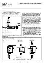
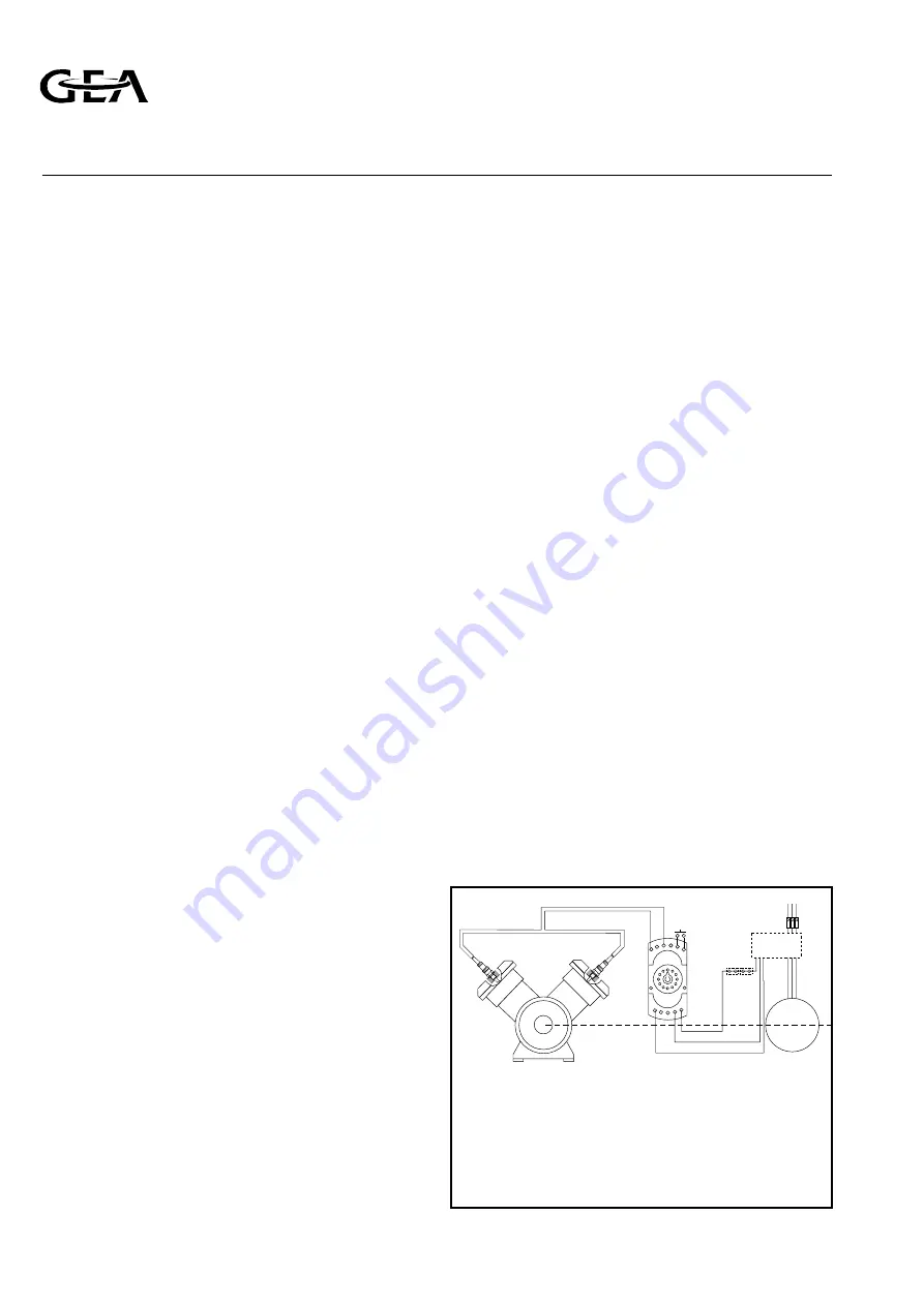
5.4 CYLINDER HEAD TEMPERATURE SAFETY
DEVICE (see fig. 5.1)
The compressor discharge temperature, measured on
the outside of the discharge line upstream the
discharge valve, must not exceed 140 °C. It is
nevertheless possible that, due to a failure, the
temperature in one or more cylinder heads suddenly
rises, in which event danger of damage arises. In
order to protect the compressor against such danger,
it can be equipped with an electronic temperature
safety device with sensing elements on all cylinders or
on some of them. This safety device interrupts the
control current circuit at a local temperature of
approx. 170 °C after which the compressor stops. The
relay to which the temperature sensing elements are
connected, is locked when cut out. A pilot lamp or
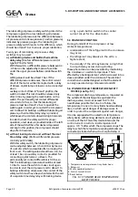
FIG. 5.1 CYLINDER HEAD TEMPERATURE
SAFETY DEVICE
M
Ê
Ë
Î
Í
Ì
Ê
1. Temperature sensing element in cylinder head
2. Relay unit
3. Motor overload protector
4. Control current circuit
5. Reset button
Refrigeration Division
Grasso
5. DISCRIPTION AND OPERATION OF ACCESSORIES
Page 5.2
Refrigeration Compressors Series RC9
v002.97.10.en


