klaxon can be connected via auxiliary contacts (see
the plant manual).
5.5 CAPACITY CONTROL
In order to adapt the compressor capacity of the
cooling load of the moment, a number of cylinders
can be put in or out of action either individually of
collectively. In this case use is made of the valve
lifting mechanism fitted on each cylinder (see
chapter 4) and operated by the pump control oil
pressure.
The capacity control may be of two-fold disign:
a) with a manually operated oil distributor
(single-stage compressors only);
b) with one up to four three-way solenoid valves
which are operated electrically and thus enable
automatic control.
Regardless of the control system applied, one or
more cylinders are connected direct to the control
oil pressure; these cylinders become automatically
operative after the unloaded starting of the
comrpessor. The other cylinders can be cut in or out
in one or more stages.
Especially in the case of two-stage compressors the
use of these switching possibilities can be limited by
the operating conditions of the installation (refer to
the plant manual). Moreover, the number of
switchings per unit of time of one individual
cylinder, as well as of the whole compressor, is tied
to a maximum (see chapter 8, Supervision during
compressor operation).
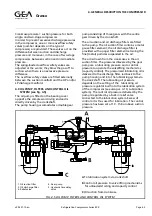
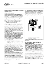
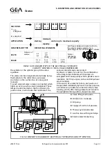
5.5.1 MANUALLY OPERATED CAPACITY
CONTROL (single-stage compressors only)
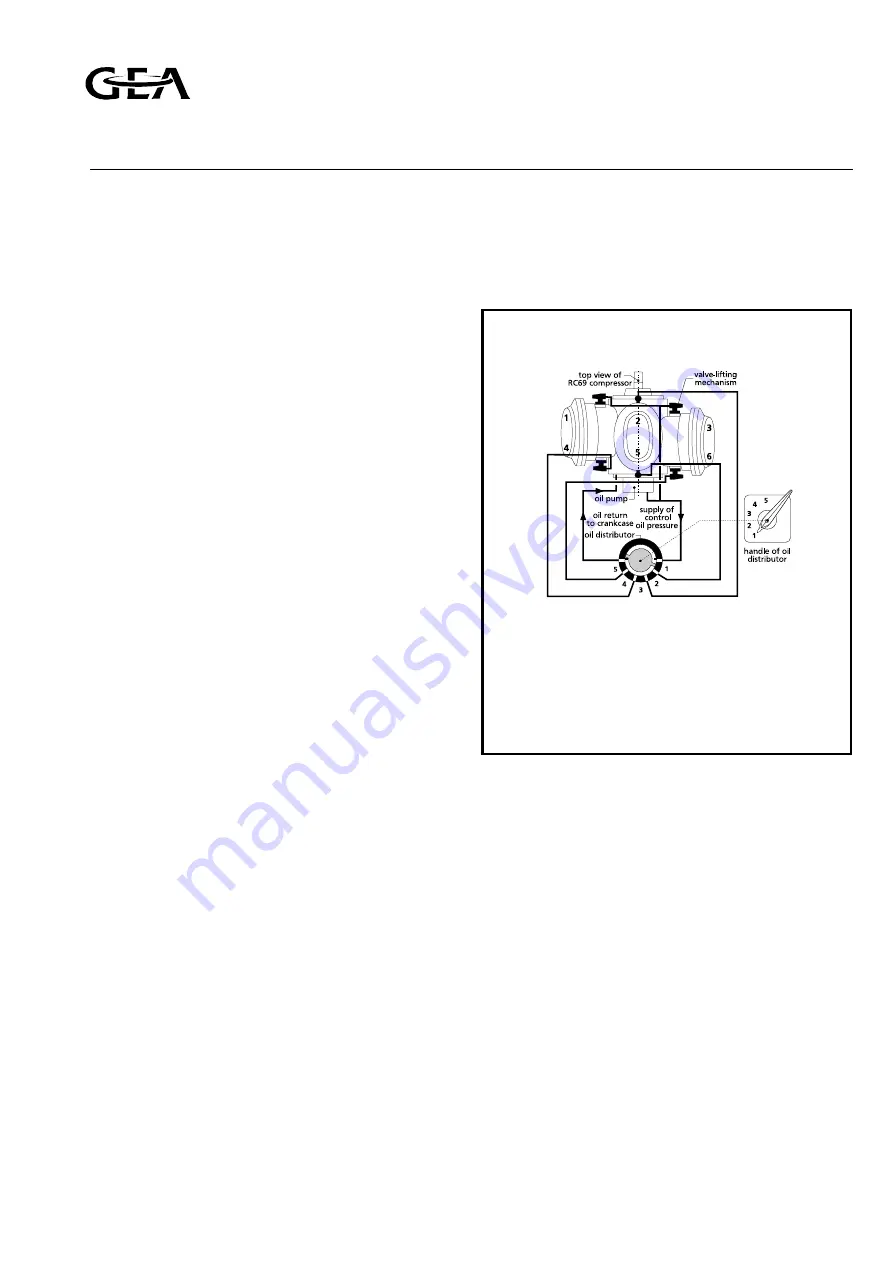
(see fig. 5.2)
In this control system the compressor is fitted with
an oil distributor which can be set by hand to
serveral positions. The distributor has six ports:
one for the control pressure connection, one for
the oil return connection and four for the
connection of the valve lifting mechanisms of the
cylinders or cylinder groups. Depeding on the
compressor size, one or more of the last-named
ports may be out of use.
The distributor has five positions. In position 1 the
control pressure is blocked and the valve lifting
mechanisms are connected to the oil return. Only
the cylinders directconnected to the control
pressure are then in operation. In the positions 2,
3, 4 and 5 the control pressure is admitted step by
step to the valve lifting mechanisms of the
connected cylinders or cylinder groups, which then
become operative.
This control system enables the compressor to be
controlled in maximum four steps from minimum
up to maximum capacity. After stopping the
compressor it is desirable to set the oil distributor
again to position 1 (also refer to chapter 7).
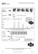
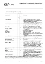
A survey of the operating cylinders in the various
positions of the oil distributor is indicated in table
5.1, overleaf.
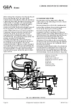
5.5.2 ELECTRICALLY OPERATED CAPACITY
CONTROL (see fig. 5.3)
For distributing the control pressure to the valve
lifting mechanisms of the cylinders or cylinder
groups, use is made in this system of one up to
four electrically operated three-way solenoid
valves; their number depends on the size of the
compressor. The solenoid valves fitted on the
compressor each have three connections: one for
the control pressure (2), one for the oil return (0)
and one for the valve lifting mechanism (1).
When the valve is not energized, the control
pressure connection in each valve is blocked, and
the valve lifting mechanism is connected to the oil
return, so that the cylinder or cylinder group is out
of action. As soon as the valve is energized, the oil
return is shut off and the control pressure is
admitted to the valve lifting mechanism, causing
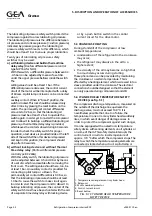
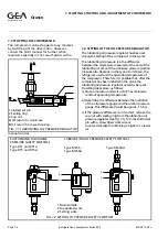
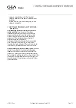
FIG. 5.2 SCHEMATIC DIAGRAM OF
THE MANUALLY OPERATED
CAPACITY CONTROL
Refrigeration Division
Grasso
5. DISCRIPTION AND OPERATION OF ACCESSORIES
v002.97.10.en
Refrigeration Compressors Series RC9
Page 5.3


