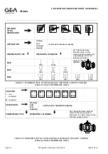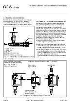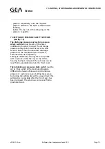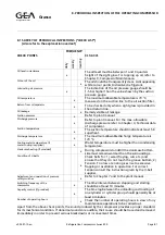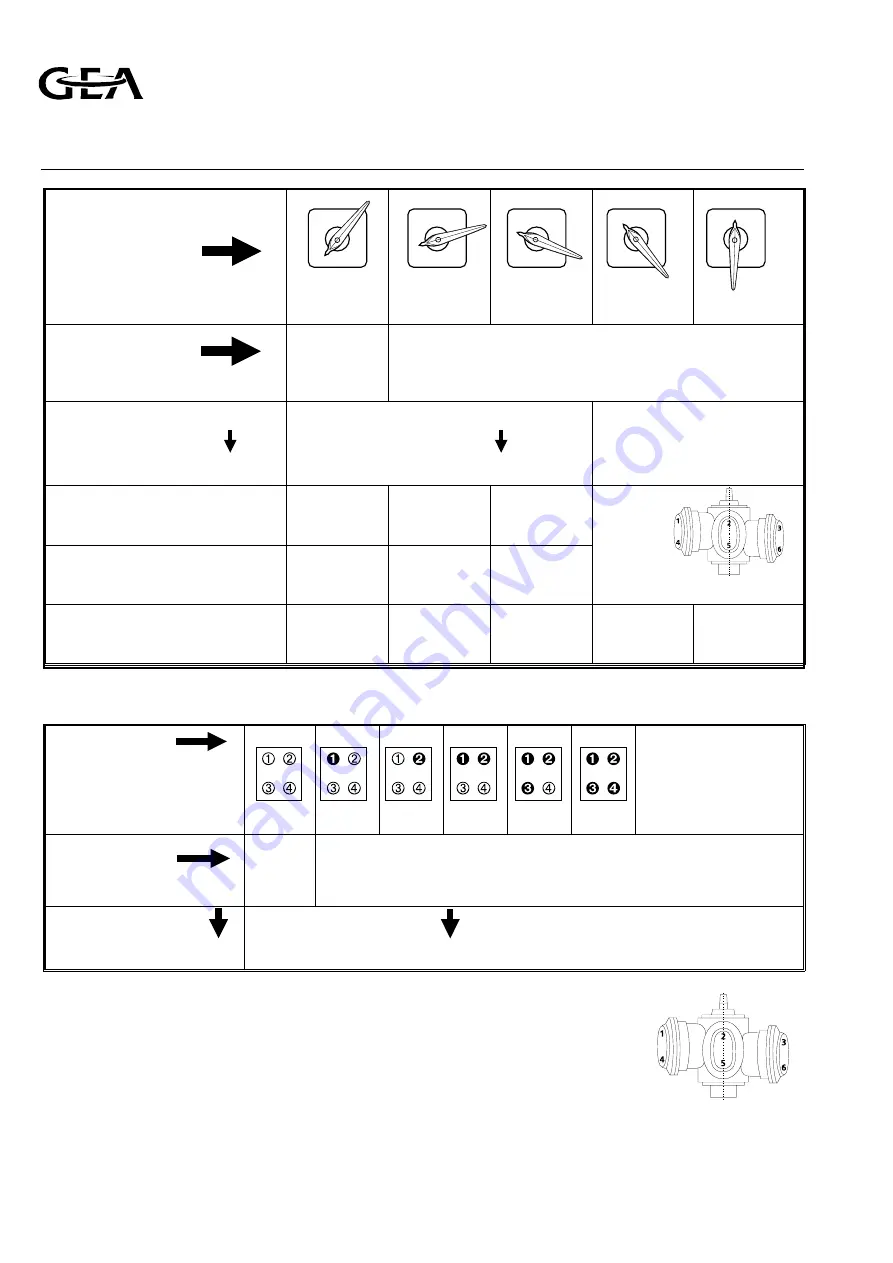
POSITION
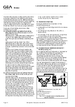
OF OIL
DISTRIBUTOR
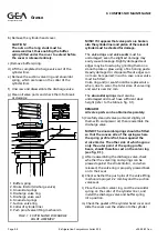
APPLICATION
starting
and
minImum
capacity
control up to maximum capacity
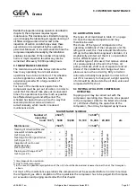
COMPRESSOR TYPE
OPERATING CYLINDERS
Each figure between
brackets refers to the
swept volume expressed as
a percentage of the full
load swept volume
RC29
1
•
(50)
1
2
(100)
Typical numbering of
cylinders
RC49
•
2
3
•
(50)
1 2
3
•
(75)
1 2
3 4
(100)
RC69
1
•
3
•
•
•
(33)
1
•
3
•
5
•
(50)
1 2 3
•
5
•
(67)
1
•
3
4 5
•
(83)
1 2 3
4 5 6
(100)
VALVE NO.
❍
non-
energized
●
energized
APPLICATION
starting
and
min.
capacity
control up to maximum capacity
COMPRESSOR TYPE
OPERATING CYLINDERS
Each figure between brackets
refers to the swept volume
expressed as a percentage of the
full load swept volume
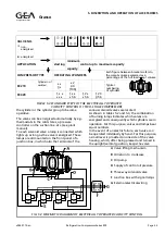
TABLE 5.2 STANDARD STEPS OF THE ELECTRICALLY OPERATED CAPACITY CONTROL
(SINGLE—STAGE COMPRESSORS ONLY)
TABLE 5.1 STANDARD STEPS OF THE MANUALLY OPERATED CAPACITY CONTROL
(SINGLE—STAGE COMPRESSORS ONLY)
1
1
1
1
1
2
2
2
2
2
3
3
3
3
3
4
4
4
4
4
5
5
5
5
5
Refrigeration Division
Grasso
5. DISCRIPTION AND OPERATION OF ACCESSORIES
Page 5.4
Refrigeration Compressors Series RC9
v002.97.10.en


