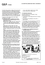
of a separate oil pump. This pump enables the oil
to be forced into the crankcase via the oil
charging valve, against suction pressure. If this oil
pump is not available, oil can be charged by
reducing the crankcase pressure to below
atmospheric pressure. the procedure is as follows:
a) Connect a hose to the oil charging valve after
removing the cap nut with gasket.
b) Fill the hose with oil and emerge its loose end in
a reservoir containing a sufficient amount of oil.
c) Close the suction stop valve to such an extent
that the suction pressure falls below the
atmospheric pressure.
d) Keep the oil charge valve open as long as the
oil in the crankcase has attained the equired
level again. Take care that no air is being drawn
into the crankcase.
e) Slowly open the suction stop valve in order to
prevent liquid hammer.
f) Remove the hose and replace the cap nut with
gasket onto the oil charging valve.
9.4 EVACUATION OF COMPRESSOR
a) Close the suction stop valve and check whether
the discharge stop valve is open.
b) Close the stop valve in the oil return line of the
oil separator.
c) In the case of two-stage compressors with
injection interstage gas cooler: shut off the
liquid lines of the interstage cooler.
In the case of two-stage compressors with flash
interstage cooler: refer to the plant manual.
d) Shunt the electric contacts of the suction
pressure safety switch.
e) Start the compressor and wait until the suction
pressure is below the atmospheric pressure.
MIND: Stop the compressor immediately as soon
as the lubricating oil pressure (i.e. the difference
between oil pressure and suction pressure)
becomes lower than 1 bar.
f) Stop the compressor and close the discharge
stop valve.
g) Close the stop valve of the discharge pressure
gauge and disconnect the line at the lower side
of the discharge pressure safety switch.
h) Fix a hose to this connection point and put its
open end at some safe place in the free air.
j) Slowly open the pressure gauge stop valve so
that the discharge gas still present in the
compressor can escape via the hose.
k) Remove the hose.
NOTE:
Connecting the line to the lower side of the
discharge pressure safety switch and removing the
shunting of the contacts in the suction pressure
safety switch should be effected only during
compressor purging after the maintenance
operations have been completed.
9.5 DRAINING AND CHANGE OF OIL
Small impurities in the refrigerant gas that are not
retained by the suction strainer (for example, fly
rust, especially in the case of NH3 installations)
eventually find their way in the lubricating oil
which thus becomes dirty. Therefor, in the case of
a new installation (or after extension or alteration
of an exisisting installation) the oil should be
renewed twice during the first 100 operating
hours of the compressor (refer to the
maintenance schedule on page 9.1).
Draining and change of oil must be carried out
with the compressor being at operating
temperature. Proceed as follows:
a) Evacuate the compressor (refer to par. 9.4).
b) Drain the oil via the oil charging valve. remove
the cover and sealing ring of one or more
service openings on the compressor side.
c) Clean the inside of the crankcase with a
non-fibrous cloth (don’t use cotton waste!);
also mind the sight glass. At the same time
clean the oil filters (refer to par. 9.6, point b)
up to and including g).
d) Fill the crankcase with fresh oil as far as possible
via the service opening(s).
e) Close the service opening(s) again by placing
the cover(s). Especially check the condition of
the sealing rings so as to prevent leakage
afterwards.
f) Fill the crankcase further with oil by means of a
separate oil pump via the oil charging valve
until the oil has reached the required level.
If no separate oil pump is available, proceed
with point g.
Refrigeration Division
Grasso
9. COMPRESSOR MAINTENANCE
Page 9.2
Refrigeration Compressors Series RC9
v003.98.11.en

