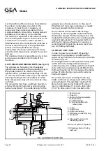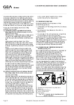
crankshaft by means of three grub screws (7.4)
and a drive pin (3) . The slip ring holder with
carbon insert can slide axially over the crankshaft
and is pressed on to the counter-slip ring by
means of the metal bellows.
O-rings (5 and 7.5) are provided to ensure the
sealing between rotary seal assembly and
crankshaft and between counter-slip ring and
shaft seal housing.
To remove sufficiently the frictional heat
developed by the slip rings, the shaft seal is
incorporated in the lubricating oil circuit (see
further Paragraph 4.10, “Lubrication system”).
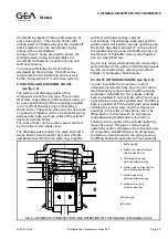
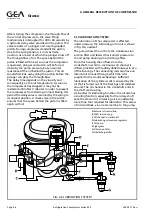
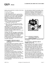
4.4 SUCTION AND DISCHARGE VALVES
(see fig. 4.3)
The suction and discharge valves of the
compressor are of the ring type. They contain
steel valve rings pressed, under spring tension, on
to a seat and shutting off the openings provided
in it. The lift of the valve rings is limited by a
stroke limitor. The suction valve only has one valve
ring retained, together with one sinusoidal spring,
between the valve seat type collar of the cylinder
liner and a stroke limitor.
The stroke limitor of the suction valve is centred
by the collar of the cylinder liner.
The discharge valve consists of a valve seat and a
stroke limitor, fixed together by means of bolts,
and between which the one valve ring, together
with four sinusoidal springs is placed
concentrically. The discharge valve seat and the
suction valve stroke limitor are one and the same.
The whole assembly is pressed on to the collar of
the cylinder liner by a powerful buffer spring. For
the function of this buffer spring, see Chapter 6,
par. 6.3, Liquid Hammer.
Fig. 4.3 only shows schematically the construction
and operation of the suction and discharge valves.
For the real construction, reference is made to
Chapter 9, Compressor Maintenance.
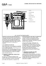
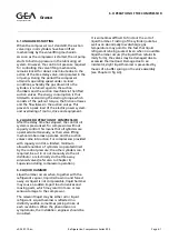
4.5 VALVE LIFTING MECHANISM (see fig. 4.4)
In order to enable the compressor to start
unloaded, all cylinders have be put out of action
mechanically by suction valve ring lifting during
compressor standstill. For this purpose a lifting
bush is provided in each cylinder, which can move
up and down around the cylinder liner. The lifting
bush is provided at the top with push pins capable
of lifting the suction valve ring from its seat via
openings in the collar of the cylinder liner. The
lifting bush is connected with an oil pressure
controlled spring-loaded piston, located in a
housing on the outside of the cylinder jacket, by
means of a lever. The piston can be moved
upward by control oil pressure from the oil pump.
At compressor standstill there is no oil pressure,
the piston is forced down by the spring causing
the lifting bush with push pins to move upwards
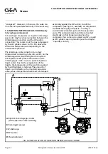
FIG. 4.3 SCHEMATIC CONSTRUCTION AND OPERATION OF SUCTION AND DISCHARGE VALVE
1. Buffer spring
2. Spring cup, also discharge
valve stroke limitor
3. Discharge valve ring
with sinusoidal springs
4. Suction valve stroke limitor,
also discharge valve seat
5. Suction valve ring
with sinusoidal springs
6. Cylinder liner, also
suction valve seat
A
Discharge
B
Suction
Refrigeration Division
Grasso
4. GENERAL DESCRIPTION THE COMPRESSOR
v002.97.10.en
Refrigeration Compressors Series RC9
Page 4.3


